4.38
SEL-751 Relay Instruction Manual Date Code 20170927
Protection and Logic Functions
Group Settings (SET Command)
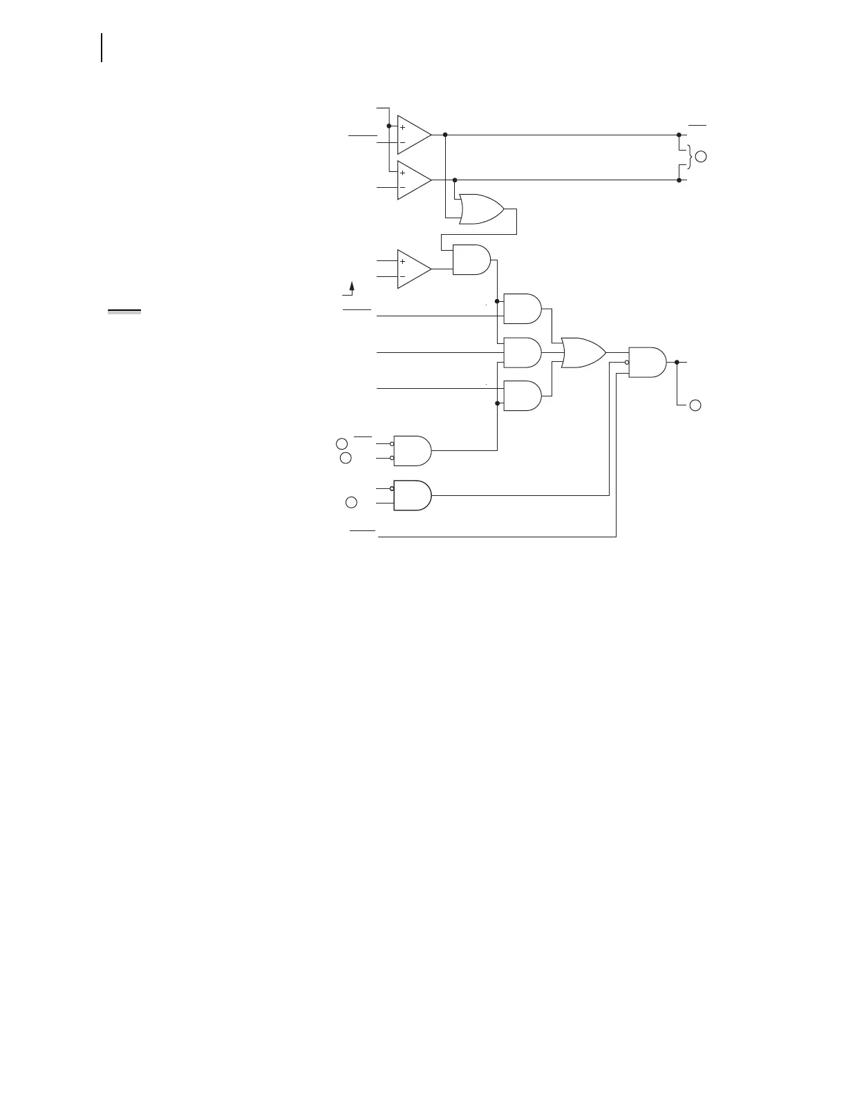
q From Figure 4.73; w to Figure 4.29 and Figure 4.31; e to Figure 4.20,
Figure 4.21, Figure 4.29, Figure 4.30, Figure 4.31, Table 4.19, and Table 4.20;
r from Figure 4.23; t from Figure 4.24.
Figure 4.25 Internal Enable (DIRNE) Logic for Zero-Sequence Voltage-
Polarized Directional Elements (Low-Impedance Grounded, Petersen Coil-
Grounded, and Ungrounded/High-Impedance Grounded Systems)
Refer to EDIRIV—SELOGIC Control Equation Enable on page 4.76 for infor-
mation on using SEL
OGIC setting EDIRIV.
VSCONN := 3V0
Loss-of-Potential
DIRNE
(Internal
Enable)
High-Impedance Grounded
ORDER = U
Ungrounded/
Petersen Coil Grounded
Low-Impedance Grounded
LOP
"P" listed in
setting ORDER
DIRVE
DIRQGE
"S" listed in
setting ORDER
EDIRIV
50NF
50NR
50NRP
50NFP
Setting
Relay
Word
Bits
Relay
Word
Bits
Settings
Settings
SELOGIC
Setting
a0N • |I
1
|
|I
N
|
|I
N
|
3
2
1
4
5
NOTE: Residual ground current I
G
is
used in place of neutral current I
N
under certain circumstances. See
Switch Between I
N
and I
G
for Low-
Impedance Grounded and
Ungrounded/High-Impedance
Grounded Systems on page 4.31.