4.27
Date Code 20170927 Instruction Manual SEL-751 Relay
Protection and Logic Functions
Group Settings (SET Command)
q Figure 4.23; w Figure 4.24; e Figure 4.25; r Table 4.19 a nd Table 4.20; t Figure 4.26; y Figure 4.27; u Figure 4.28; i Figure 4.29;
o Figure 4.30; a Figure 4.32; s Figure 4.33; d Figure 4.34; f Figure 4.35; g Figure 4.9; h Figure 4.2; j Figure 4.8; k Figure 4.2;
l Figure 4.21.
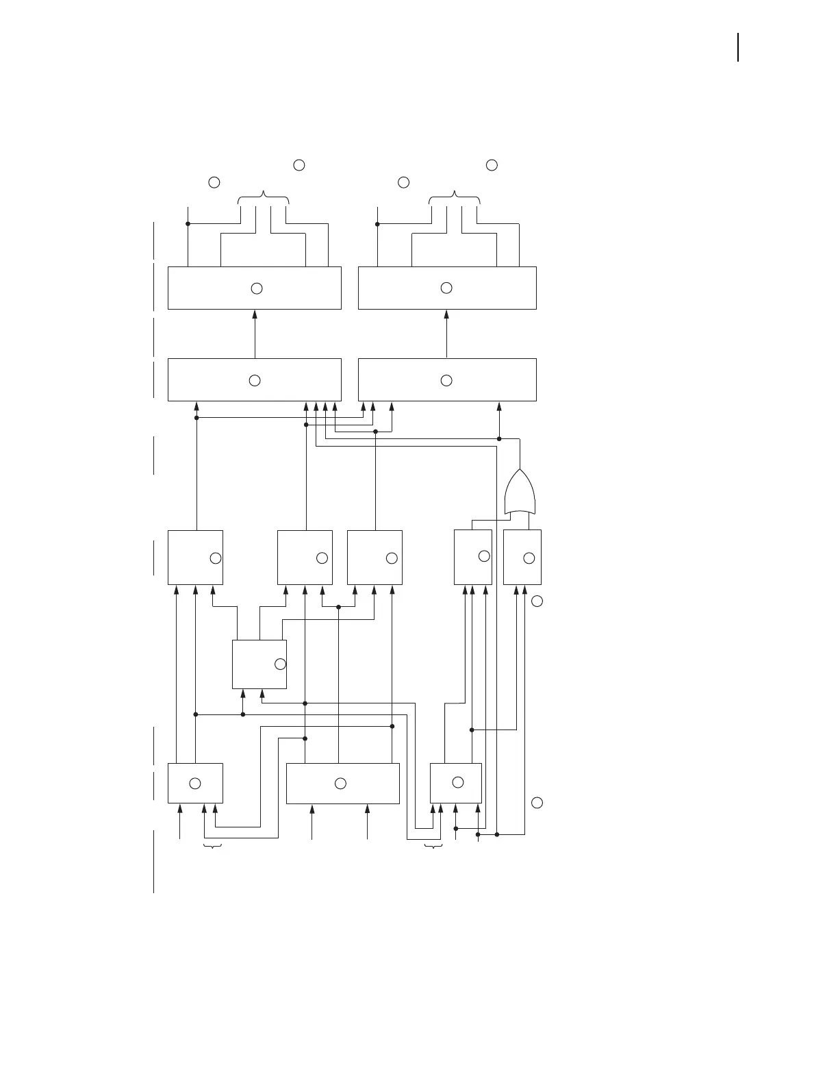
Figure 4.20 General Logic Flow of Directional Control for Neutral Ground and Residual Ground Overcurrent Elements (Excluding Ungrounded/High-Impedance
Grounded Systems)
DIRIE
"I" listed
in setting
ORDER
FDIRN/
RDIRN
FDIRI/
RDIRI
Channel IN
Current-
Polarized
"I", "S", "P" (and "U" in ) are mutually exclusive choices for setting ORDER (see ).
DIRNE
50NF/
50NR
Disable
Inputs
Disable
Inputs
Petersen Coil
Low-
Impedance
to Neutral Ground
Time-Overcurrent
Elements
to Neutral Ground
Inst./Def.-Time
Overcurrent
Elements
Level 1
N1DIR
Level 2
N2DIR
Level 3
N3DIR
Level 4
N4DIR
DIRNF/
DIRNR
Best Choice
Ground
Directional
Logic
Zero-Sequence
Voltage-
Polarized
Negative-
Sequence
Voltage-
Polarized
DIRVE
"V" listed
in setting
ORDER
"S" listed in
setting ORDER
"P" listed in
setting ORDER
"Q" listed
in setting
ORDER
DIRQGE
50QF/
50QR
50GF/
50GR
FDIRV/
RDIRV
FDIRQG/
RDIRQG
DIRGF/
DIRGR
Level 1
G1DIR
Level 2
G2DIR
Level 3
G3DIR
Level 4
G4DIR
to Residual Ground
Inst./Def.-Time
Overcurrent
Elements
to Residual Ground
Time-Overcurrent
Elements
Enable Directional
Elements with
Setting ORDER
Internal
Enables
Relay Word
Bit Outputs
Directional
Elements
Relay Word
Bit Outputs
Relay Word
Bit Outputs
Direction
Forward/
Reverse Logic
Directional
Control
Directional
Element
Routing
5
4
6
7
12
14
13
17
16
15
10
11
8
9
418
1
2
3