4.176
SEL-751 Relay Instruction Manual Date Code 20170927
Protection and Logic Functions
Global Settings (SET G Command)
Arc-Flash Overcurrent Elements (50PAF, 50NAF)
Table 4.73 shows the settings for the arc-flash instantaneous overcurrent ele-
ments. Two elements are provided; the three-phase overcurrent element
50PAF and the neutral overcurrent element 50NAF.
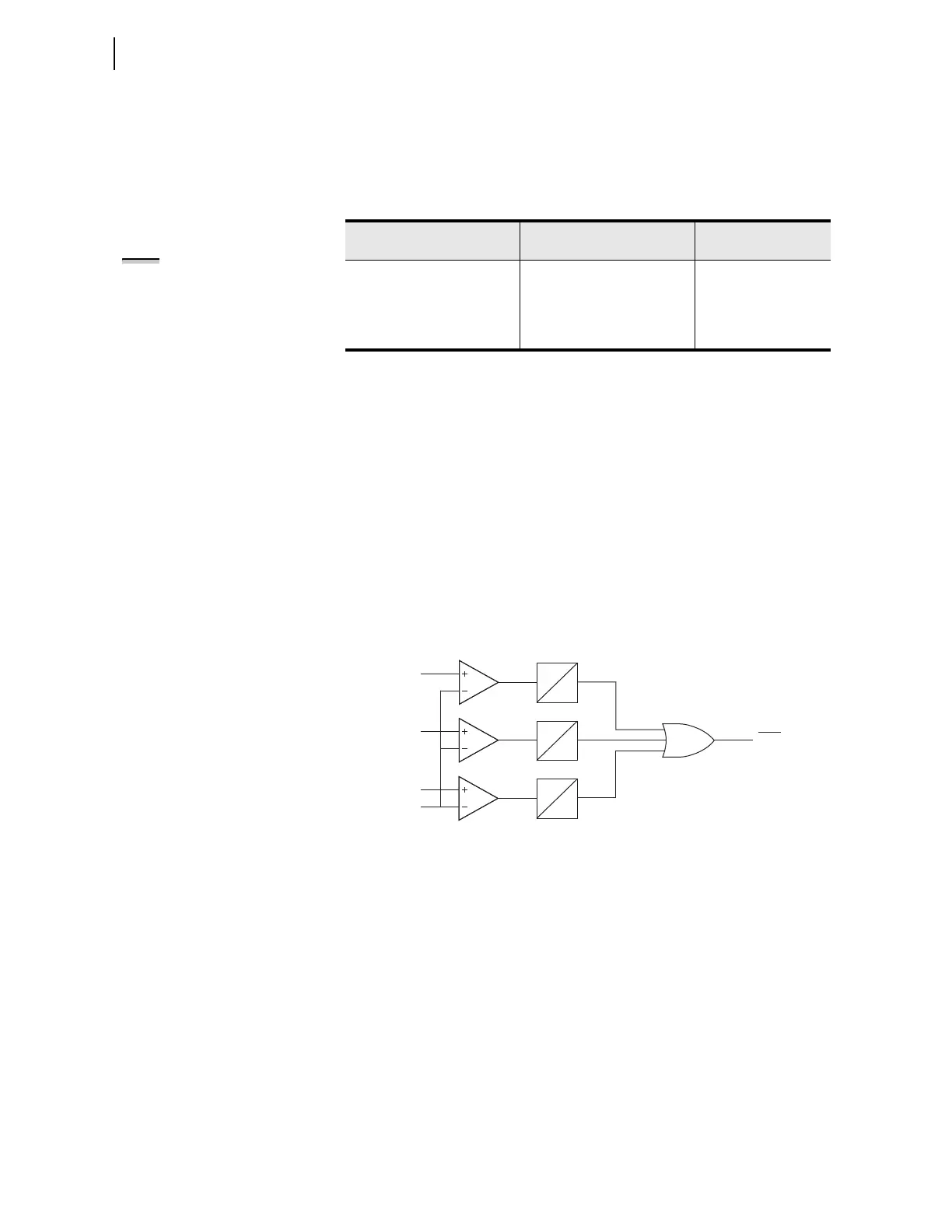
The arc-flash overcurrent elements use raw A/D converter samples, with the
sampling rate of 16 samples per cycle. Individual samples are compared with
the setting threshold as shown in Figure 4.102, followed by a security counter
requiring that two samples in a row be greater than the setting threshold.
Although both elements operate on instantaneous current values, additional
scaling is applied to present settings in the user-friendly “rms” format.
Fast overcurrent detectors do not reject harmonics and therefore have a natural
tendency to “overreach” under high harmonic load conditions. To avoid unin-
tended element pickup, Arc-flash trip level 50PAFP should be set at least 2
times the expected maximum load. Temporary activation of the arc-flash over-
current element during inrush/load pickup conditions is expected and is nor-
mally taken into account by the arc-flash “light based” supervision.
Figure 4.102 Arc-Flash Instantaneous Overcurrent Element Logic
Arc-Flash Time-Overlight Elements (TOL1 through TOL8)
The SEL-751 offers as many as eight fiber-optic light sensor inputs. Each
input is associated with one inverse time-overlight element offering enhanced
security coupled with exceptionally fast operation. Shape of the inverse-time
characteristic is fixed offering robust rejection of unrelated light events with-
out adding unnecessary settings. Table 4.74 shows the arc-flash time-overlight
element settings.
Each sensor channel has a user selectable sensor type (NONE, POINT, or FIBER)
representing the type of sensor installed. Keyword POINT represents a point sensor,
while the keyword FIBER represents a clear-jacketed fiber loop sensor.
Table 4.73 Arc-Flash Overcurrent Settings
Setting Prompt Setting Range
Setting Name :=
Fac to ry Defa ult
AF PH OC TRP LVL OFF, 0.50–100.00 A
a
a
For I
NOM
= 5 A (Phase and Neutral respectively).
50PAFP := OFF
0.10–20.00 A
b
b
For I
NOM
= 1 A (Phase and Neutral respectively).
AF N OC TRP LVL OFF, 0.50–100.00 A
a
50NAFP := OFF
0.10–20.00 A
b
NOTE: The 50NAFP setting is not
available with the 0.2 A neutral
channel option.
2
16
50PAF
Relay
Word
Bit
2
16
2
16
IA Sample
IB Sample
IC Sample
Setting 50AFP
Scaled to
Equivalent Sample
50PAF Element Shown, 50NAF Element is Similar, responds to current measured by the IN input.