4.120
SEL-751 Relay Instruction Manual Date Code 20170927
Protection and Logic Functions
Group Settings (SET Command)
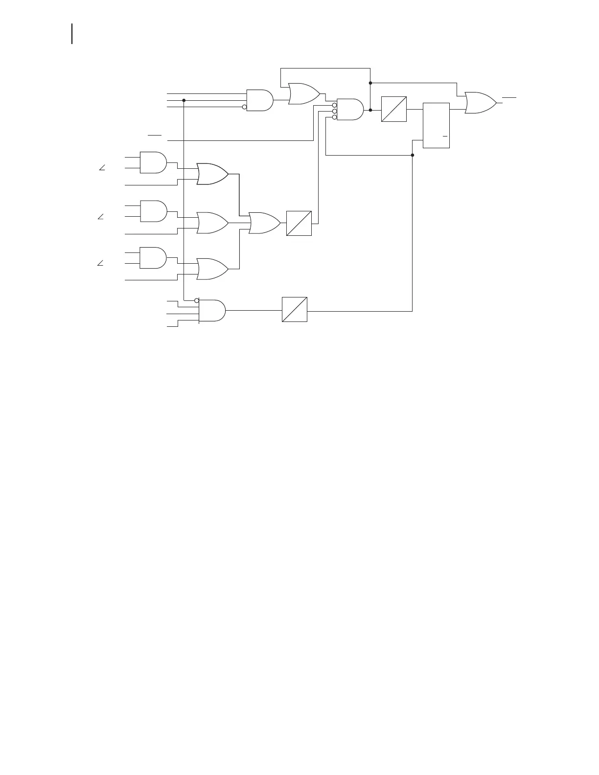
Figure 4.73 Loss-of-Potential (LOP) Logic
LOP Monitoring and Alarms
You should take steps to immediately correct an LOP problem so that normal
protection is rapidly re-established. Include the LOP Relay Word bit in an out-
put contact alarm to notify operation personnel of abnormal voltage input con-
ditions and failures that can be detrimental to the protection system
performance if not quickly corrected.
Vector Shift Element
The vector shift element is used to detect islanding conditions of distributed
generators (DGs) or loss of mains, and disconnect these DGs from the utility
network under these conditions. Failure to trip islanded generators can lead to
problems relating to out-of-synchronism reclosing, equipment damage, unsta-
ble operation, degradation of power quality and personnel safety.
The vector shift element in the SEL-751 is designed for applications where a
DG is connected to either the utility or other main generators that require fast
disconnection upon detection of an islanding condition. The vector shift ele-
ment operates within three cycles providing fast and reliable island detection;
this operating time is fast enough to prevent out-of-synchronism reclosing of
the network feeders avoiding generator damage and any adverse affects.
Islanding is a three-phase phenomenon: therefore, the vector shift monitoring
is performed on all of the three phases of the voltage signals. Detection of a
vector shift condition occurs when there are sudden phase variations on all
three phases of the voltage waveforms. At the moment of islanding, the sud-
den change in load current causes a sudden change in the periods of the volt-
age signals. This element measures the difference in the present period
duration and a reference period (as explained below). This difference is then
converted to degrees and compared against the user-defined setting
78VSAPU.
1 s
S
R
Q
Q
0
0
1 s
1 cyc
0
LOP
| V
1
| > 10.5 V
Δ | V
1
| > 20%
Δ | I
1
| > 0.1 • I
NOM
Δ | I
2
| > 0.1 • I
NOM
Δ | I
0
| > 0.1 • I
NOM
| V
2
| < 5 V
| V
0
| < 5 V
| V
1
| > 0.75 • Nominal Voltage
(RESET has priority)
Note: I
NOM
is 1 A or 5 A depending on the part number.
I
NOM
is the phase secondary input rating.
Relay
Word
Bit
V
NOM
= OFF
Δ I
1
> 10°
| I
1
| > 0.1 • I
NOM
Δ I
2
> 10°
| I
2
| > 0.1 • I
NOM
Δ I
0
> 10°
| I
0
| > 0.1 • I
NOM
LOPBLK
SELOGIC
Setting