2.25
Date Code 20170927 Instruction Manual SEL-751 Relay
Installation
Relay Connections
I/O Diagram
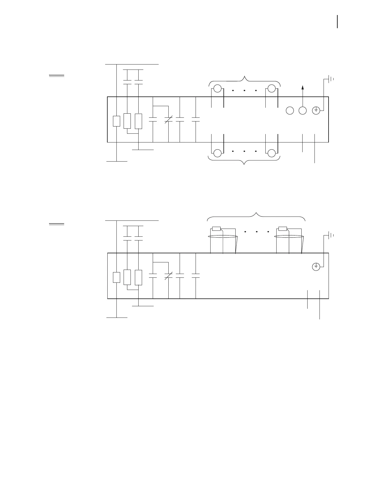
A more functional representation of two of the control (I/O) connections is
shown in Figure 2.15 and Figure 2.16.
Figure 2.15 Control I/O Connections—4 AI/4 AO Option in Slot D and Fiber-Optic Port in Slot B
Figure 2.16 Control I/O Connections—Internal RTD Option in Slot D
Fiber-Optic Cable
to SEL-2600 Series
+IRIG-B
–IRIG-B
IRIG-B
PS
A01
A02
–/N
+/H
External
Contacts
SEL-751 Relay
RX
D07
+
As Many as Four
Analog Outputs
D08
—
B01 B02
IN101
IN102
A10
A11
A12 A07
A08
OUT103
+
D15
—
D16
D02
—
—
D10
D01
+
+
D09
A03
A04
OUT101
A05
A06
OUT102
A09
TX
As Many as Four
Analog Inputs
AO401 AO404
AI401 AI404
++
++
NOTE: All digital inputs
and digital outputs
(including high-current,
high-speed hybrid)
connections are polarity
neutral.
PS
A01
A02
–/N
+/H
External
Contacts
SEL-751 Relay
IN101
IN102
A10
A11
A12
+IRIG-B
–IRIG-B
IRIG-B
B01 B02
A07
A08
OUT103
A03
A04
OUT101
A05
A06
OUT102
A09
D03
COMP/
SHLD
D02
—
D01
+
RTD01
D30
COMP/
SHLD
D29
—
D28
+
RTD10
As Many as Ten
RTD Inputs
NOTE: All RTD
Comp/Shield terminals
are internally connected
to the relay chassis and
ground.
Notes:
➤ The chassis ground connector located on the
rear-panel card Slot A must always be
connected to the local ground mat.
➤ Power supply rating (110–240 Vac,
110–250 Vdc or 24–48 Vdc) depends on
relay part number.
➤ Optoisolated inputs IN101 and IN102 are
standard and located on the card in Slot A.
➤ All optoisolated inputs are single-rated: 24,
48, 110, 125, 220, or 250 Vac/Vdc. Standard
inputs IN101/102 can have a different rating
than the optional IN401/402/403/404 (not
shown).
➤ Output contacts OUT101, OUT102, and
OUT103 are standard and are located on
the card in Slot A.
➤ The analog (transducer) outputs shown
are located on the optional I/O
expansion card in Slot D.
➤ The fiber-optic serial port is located on
the card in Slot B. A Simplex 62.5/125
µm fiber-optic cable is necessary for
connecting to an SEL-2600 Series RTD
Module. This fiber-optic cable should be
1000 meters or shorter.