4.62
SEL-751 Relay Instruction Manual Date Code 20170927
Protection and Logic Functions
Group Settings (SET Command)
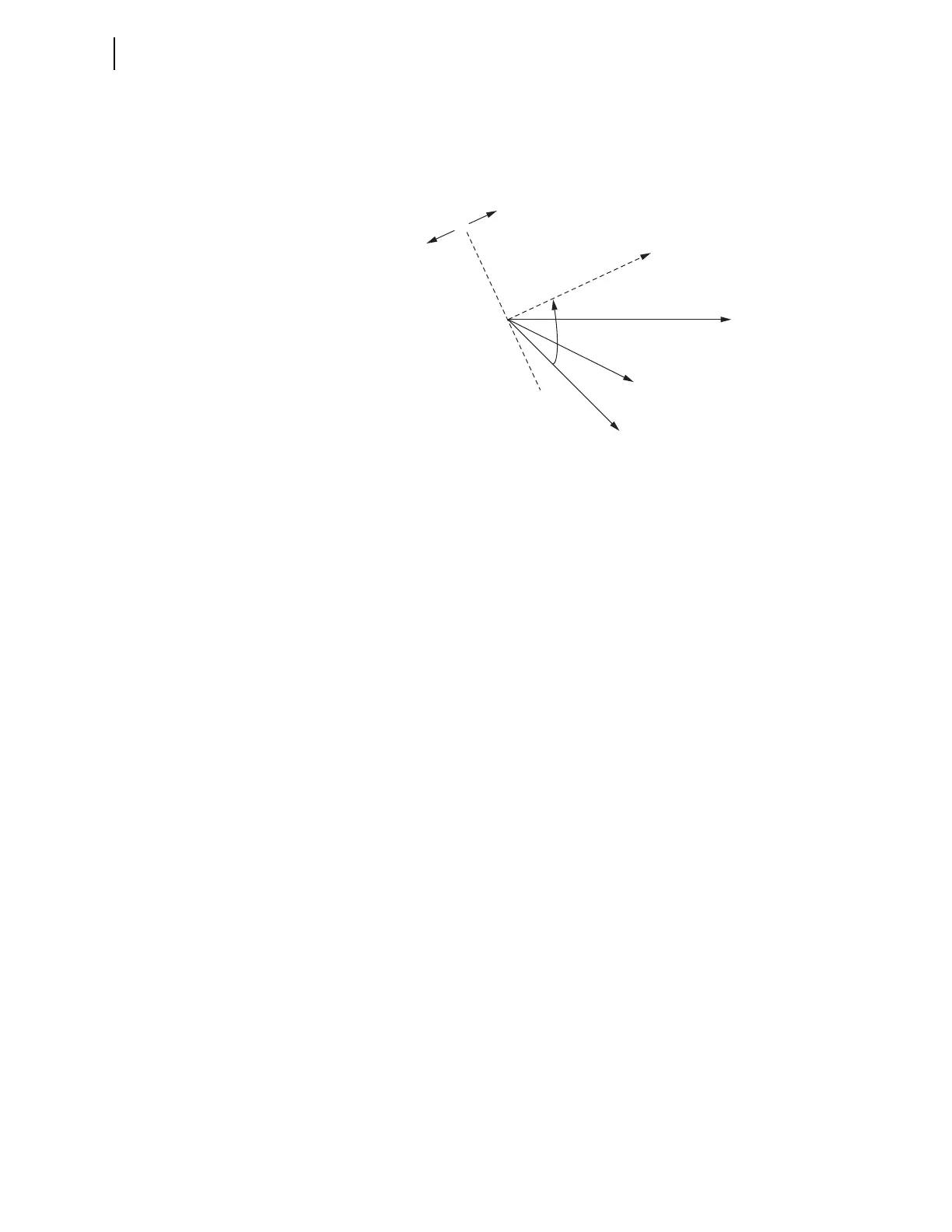
In certain impedance grounded systems with high line charging capacitance,
capacitive currents can cause the traditional element to improperly declare
reverse currents as forward, causing unfaulted circuits to trip during ground
faults. This can be prevented by adjustment of the maximum torque angle
using the setting INMTA, as shown in Figure 4.43.
Figure 4.43 Current-Polarized Directional Element Characteristic When
INMTA 0.00
KGN—Neutral Restraint Factor
If setting ORDER does not contain I (no channel IN current-polarized direc-
tional elements are enabled), or EDIR := N, or EDIR := AUTO, then setting
KGN is not made or displayed and KGN is set to OFF internally.
When traditional operation of the Channel IN Current-Polarized Directional
Element is desired, set KGN := OFF. With this setting, the maximum torque
line of the element is in phase with the polarizing current, I
N
, that is, INMTA
is effectively 0 (see Figure 4.42). This is the proper setting for solidly-
grounded and most impedance grounded applications.
When KGN is set to a value other than OFF, the measured residual current,
IG, must be greater than KGN • I
N
• CTRN/CTR before the element is
allowed to operate (see Figure 4.24). This provides additional security for the
directional element when there is false residual current because of mismatch
of the phase CTs of an unfaulted feeder. The neutral channel current, I
N
, is
scaled by CTRN/CTR to place it on the same base as the residual current, I
G
.
INMTA—Neutral Maximum Torque Angle
If KGN := OFF, then setting INMTA is not made or displayed and INMTA is
set to 0 internally.
The polarizing quantity I
N
of the Channel IN Current-Polarized Directional
Element is rotated INMTA degrees counter-clockwise (see Figure 4.43).
See the technical paper Selecting Directional Elements for Impedance-
Grounded Distribution Systems by Ronald Lavorin, Daqing Hou, Hector J.
Altuve, Normann Fischer, and Fernando Calero, available on the SEL website
for more information on how to determine the settings for KGN and INMTA.
a0—Positive-Sequence Current Restraint Factor, I
0
/I
1
If setting ORDER does not contain V or I (no zero-sequence voltage-polarized
or channel IN current-polarized directional elements are enabled), then setting
a0 is not made or displayed.
V
A
Reverse
Forward
I
N
INMTA
Maximum
Torque
Line
I
G