4.118
SEL-751 Relay Instruction Manual Date Code 20170927
Protection and Logic Functions
Group Settings (SET Command)
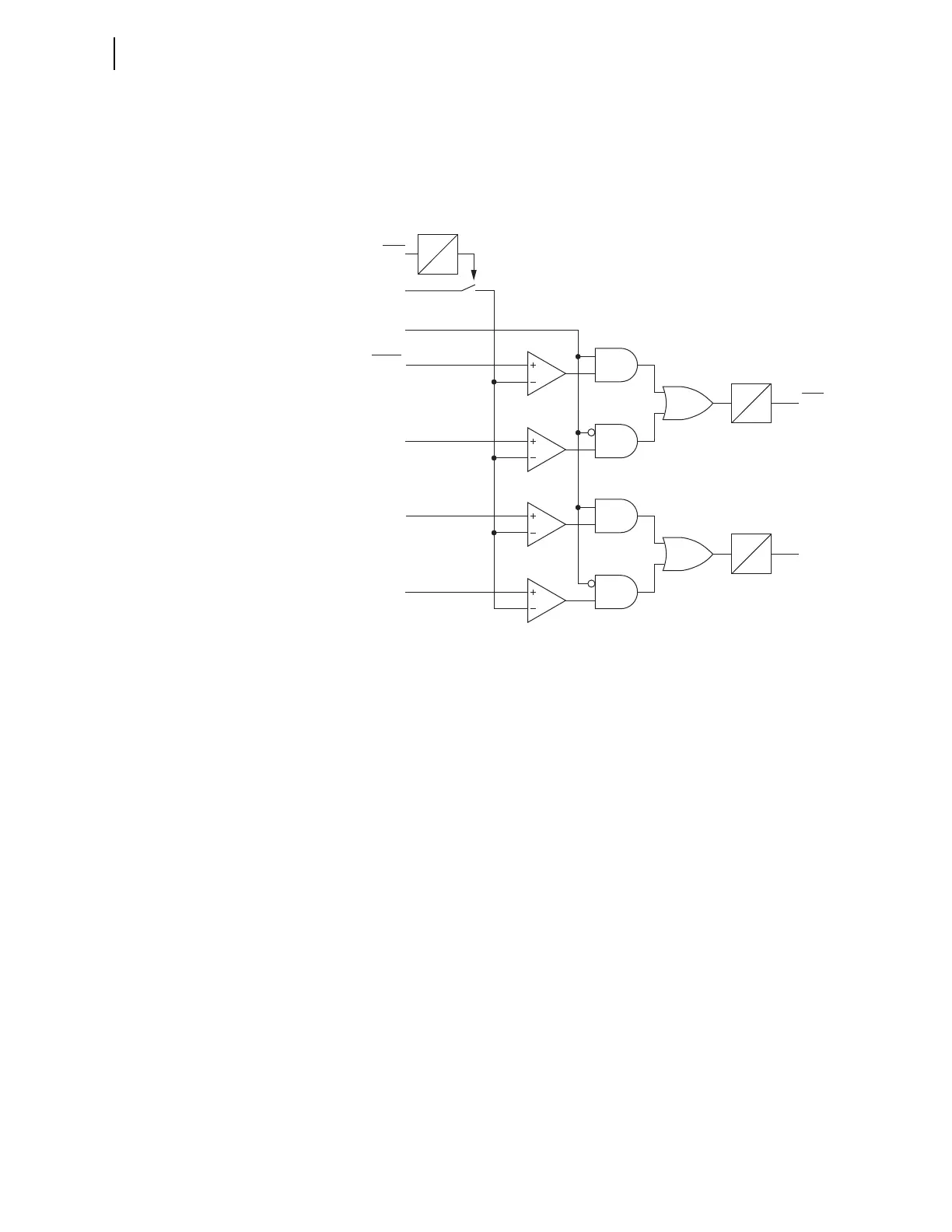
asserted (breaker closed), however when 55DLY := 0 the element is always
enabled irrespective of the 52A status. Figure 4.72 shows the logic diagram
for the power factor elements. You can use these elements to detect synchro-
nous motor out-of-step or loss-of-field conditions. Refer to Figure 5.1 for the
relay power measurement convention.
Figure 4.72 Power Factor Elements Logic
Loss-of-Potential
(LOP) Protection
The SEL-751 sets Relay Word bit LOP (loss-of-potential) upon detecting a
loss of relay ac voltage input such as that caused by blown potential fuses or
by the operation of molded-case circuit breakers. Because accurate relaying
potentials are necessary for certain protection elements (undervoltage 27 ele-
ments, for example), you can use the LOP function to supervise these protec-
tion elements. Refer to Figure 4.73 for the LOP logic.
The relay declares an LOP when there is more than a 20 percent drop in the
measured positive-sequence voltage (V1) with no corresponding magnitude or
angle change (greater than a pre-determined threshold) in positive-sequence
(I1), negative-sequence (I2), or zero-sequence currents (I0).
If this condition persists for 1 second, then the relay latches the LOP Relay
Word bit at logical 1. The relay resets LOP when the positive-sequence volt-
age (V1) returns to a level greater than 0.75 • Nominal Voltage while negative-
sequence voltage (V2) and zero-sequence voltage (V0) are both less than 5 V
secondary (VNOM is a relay setting).
Measured
Power Factor
52A
PF Leading
55LDAP
55LGAP
55A
0
55AD
Relay
Word
Bits
Relay
Word
Bit
Settings
55LDTP
55LGTP
55T
0
55TD
0
55DLY