E.10
SEL-751 Relay Instruction Manual Date Code 20170927
Modbus RTU Communications
Communications Protocol
Coil addresses start at 0000 (i.e., Coil 1 is located at Coil address 0000). If the
device is disabled or the breaker jumper is not installed, the device responds
with error code 4 (Device Error). In addition to Error Code 4, the device
responses to errors in the query are shown in Ta ble E.15.
06h Preset Single
Register Command
The SEL-751 uses this function to allow a Modbus master to write directly to
a database register. Refer to the Modbus Register Map in Table E.34 for a list
of registers that you can write by using this function code. If you are
accustomed to 4X references with this function code, for six-digit addressing,
add 400001 to the standard database addresses.
In Table E.16, the command
response is identical to the command the master required.
76 01, 05 Pulse RB18
a
77 01, 05 Pulse RB19
a
78 01, 05 Pulse RB20
a
79 01, 05 Pulse RB21
a
80 01, 05 Pulse RB22
a
81 01, 05 Pulse RB23
a
82 01, 05 Pulse RB24
a
83 01, 05 Pulse RB25
a
84 01, 05 Pulse RB26
a
85 01, 05 Pulse RB27
a
86 01, 05 Pulse RB28
a
87 01, 05 Pulse RB29
a
88 01, 05 Pulse RB30
a
89 01, 05 Pulse RB31
a
90 01, 05 Pulse RB32
a
a
Pulsing a Set remote bit will cause the remote bit to be cleared at the end of the pulse
(1 SEL
OGIC Processing Interval).
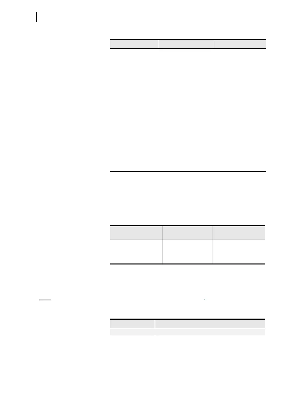
Table E.15 Responses to 05h Force Single Coil Query Errors
Error Error Code Returned
Communications Counter
Increments
Invalid bit (coil) Illegal Data Address (02h) Invalid Address
Invalid bit state requested Illegal Data Value (03h) Illegal Register
Format Error Illegal Data Value (03h) Bad Packet Format
Table E.14 01h, 05h SEL-751 Output (Sheet 3 of 3)
Coil Address (Decimal) Function Code Supported Coil Description
Table E.16 06h Preset Single Register Command (Sheet 1 of 2)
Bytes Field
Queries from the master must have the following format:
1 byte Slave Address
1 byte Function Code (06h)
2 bytes Register Address
NOTE: When setting EN_LRC := Y
(see Table 9.4), the Relay Word bit
LOCAL supervises the CC and OC
bits. If the LOCAL bit is asserted
(LOCAL = 1), the relay does not set
the CC or OC bits. The Relay Word bit
LOCAL is determined by the LOCAL
SEL
OGIC control equation (see
Tab le 9.4 ).