4.66
SEL-751 Relay Instruction Manual Date Code 20170927
Protection and Logic Functions
Group Settings (SET Command)
A grounding bank is installed if low-impedance grounding is desired at a sub-
station and the transformer bank is to remain ungrounded. Figure 4.46 also
shows a ground fault out on Feeder 1 (a forward fault from the perspective of
Relay 1). This example assumes that SEL-751 relays (Relay 1, Relay 2, etc.)
are installed at feeder positions in a distribution substation.
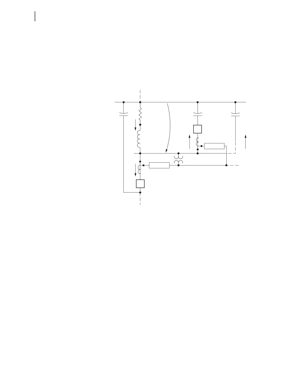
Figure 4.47 shows the resultant zero-sequence impedance network for the
ground fault on Feeder 1 in Figure 4.46. V
0
in Figure 4.47 is the zero-
sequence voltage seen by all the relays connected to the distribution substation
bus three-phase voltage.
Figure 4.47 Zero-Sequence Impedance Network for Low-Impedance
Grounded Distribution System With a Ground Fault on Feeder 1
Impedance definitions for Figure 4.47:
➤ –jXC
0(1)
= zero-sequence capacitive reactance for Feeder 1 (the
faulted feeder)
➤ –jXC
0(2)
= zero-sequence capacitive reactance for Feeder 2
➤ –jXC
0(n)
= zero-sequence capacitive reactance for the
cumulative other feeders
➤ Z
0T
= transformer bank (or grounding bank) zero-sequence
impedance
➤ R
G
= neutral resistance, connected to transformer bank (or
grounding bank)
The zero-sequence capacitive reactance values of the feeders are much larger
than the zero-sequence feeder line impedances, so the zero-sequence feeder
line impedances are ignored in this fault analysis.
Current definitions for Figure 4.47:
➤ I
0(1)
= zero-sequence current flow for Feeder 1 (forward
direction for Relay 1)
➤ I
0(2)
= zero-sequence current flow for Feeder 2 (forward
direction for Relay 2)
Neutral
Resistance
I
0G
Z
0T
Transformer
Bank (or
Grounding
Bank)
—jXC
0(1)
3R
G
—jXC
0(2)
—jXC
0(n)
Feeder 2
Feeder n
Relay 1
V
0
2
Relay 2
I
0(2)
I
0(n)
1
I
0(1)
Feeder 1
Zero-Sequence Reference Bus