4.67
Date Code 20170927 Instruction Manual SEL-751 Relay
Protection and Logic Functions
Group Settings (SET Command)
➤ I
0(n)
= zero-sequence current flow for cumulative other feeders
(forward direction for relays on other feeders)
➤ I
0G
= zero-sequence current flow through neutral resistance R
G
and transformer bank (or grounding bank)
Presume there is a substantial capacitance-creating network (e.g., under-
ground cable) on the individual feeders. As cable capacitance increases,
capacitive reactance decreases, allowing for increased capacitive current flow.
For the ground fault in Figure 4.46 (a reverse fault from the perspective of
Relay 2), Relay 2 sees zero-sequence current I
0(2)
flow toward the zero-
sequence capacitive reactance –jXC
0(2)
. If this current flow is high enough, a
false trip may occur, unless otherwise prevented (e.g., by directional control).
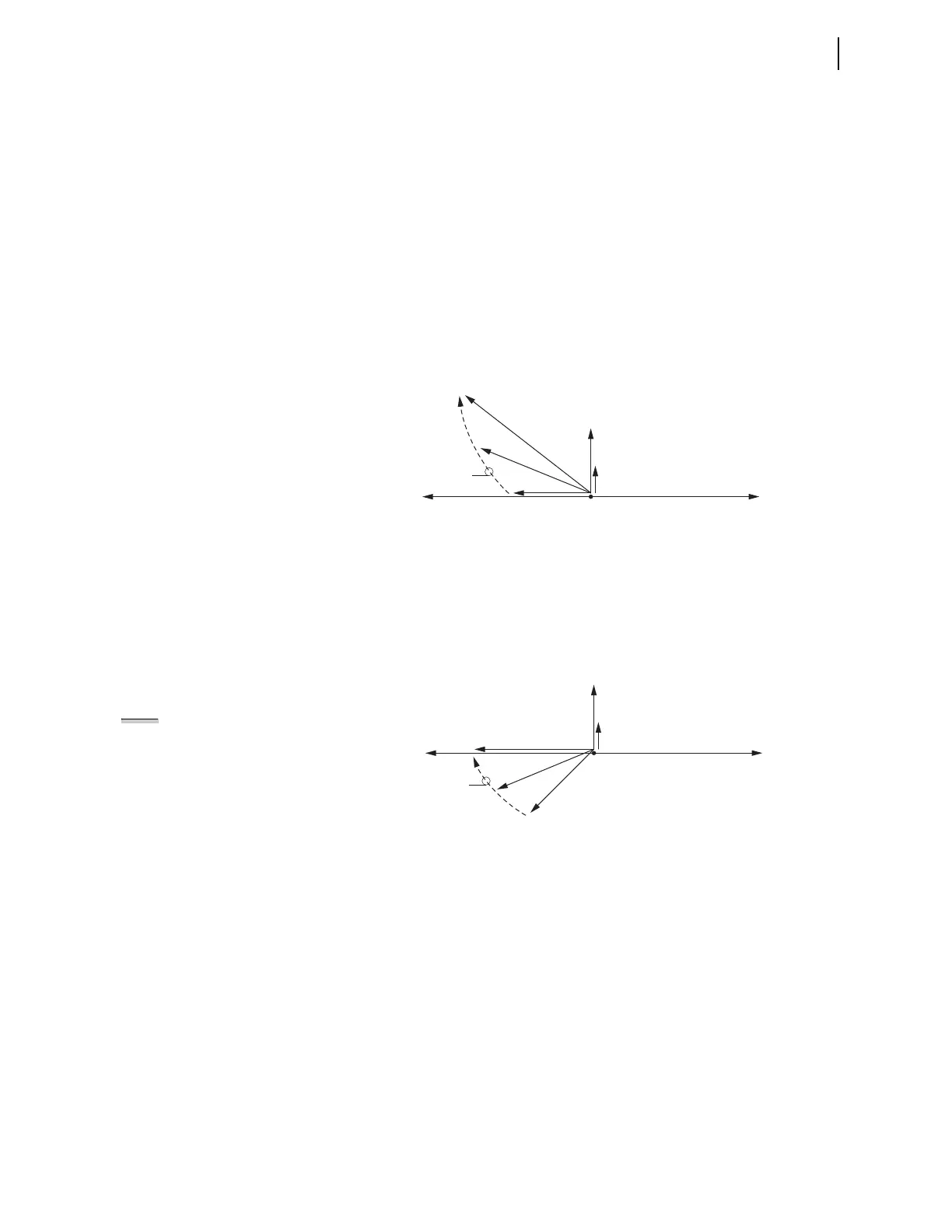
Figure 4.48 plots the increase in zero-sequence current I
0G
resulting from
decreasing neutral resistance R
G
.
Figure 4.48 Decreasing Neutral Resistance R
G
Results in Increasing Zero-
Sequence Current I
OG
Vectorially add currents I
0(2)
and I
0(n)
to I
0G
(per direction in Figure 4.47):
Figure 4.49 plots the increase in zero-sequence current I
0(1)
(seen by Relay 1)
resulting from decreasing neutral resistance R
G
.
Figure 4.49 Decreasing Neutral Resistance R
G
Results in Increasing Zero-
Sequence Current I
0(1)
(Seen by Relay 1)
In Figure 4.49, the lowest magnitude of zero-sequence current I
0(1)
(at
225 degrees from zero-sequence voltage V
0
) represents a high-resistance
grounded system. The following (absolute value) comparisons are typically
true for a high-resistance grounded system:
➤ 3R
G
>> Z
0T
(ignore transformer bank [or grounding bank]
impedance Z
0T
)
➤ 3R
G
= resultant impedance from the parallel combination of
zero-sequence capacitive reactance values –jXC
0(2)
and
–jXC
0(n)
(the total capacitive reactance behind Relay 1)
As neutral resistance R
G
decreases, zero-sequence current I
0(1)
increases in
Figure 4.49. The system is moving away from being a high-resistance
grounded system toward being a low-resistance grounded system.
V
0
I
0(2)
I
0(n)
I
0G
I
0G
I
0G
—V
0
Decreasing R
G
V
0
I
0(2)
I
0(n)
I
0(1)
I
0(1)
I
0(1)
—V
0
Decreasing R
G
NOTE: APPLY Z0MTA TO
HIGH- RESISTANCE
GROUNDED SYSTEM?
This example for the Z0MTA setting
discussion addresses low-impedance
grounded systems. A high-resistance
grounded system (with its lower zero-
sequence current values for ground
fault conditions) requires that channel
IN be connected to a separate current
transformer, instead of in a factory-
standard residual connection with the
phase current channels.
Such a separate current transformer
would have the three primary phase
wires running through its core,
eliminating any false residual current.
Such current transformer applications
are often referred to by one of the
following names: flux-summing, core-
balance, zero-sequence, ground fault,
or window current transformers.
Other settings (see Figure 4.24 and
Figure 4.27) also have to be
considered to make sure they are
sensitive enough for a high-resistance
grounded system application.
The technical paper referenced at the
end of this subsection also discusses
directional element applications for
high-resistance grounded systems.