4.179
Date Code 20170927 Instruction Manual SEL-751 Relay
Protection and Logic Functions
Global Settings (SET G Command)
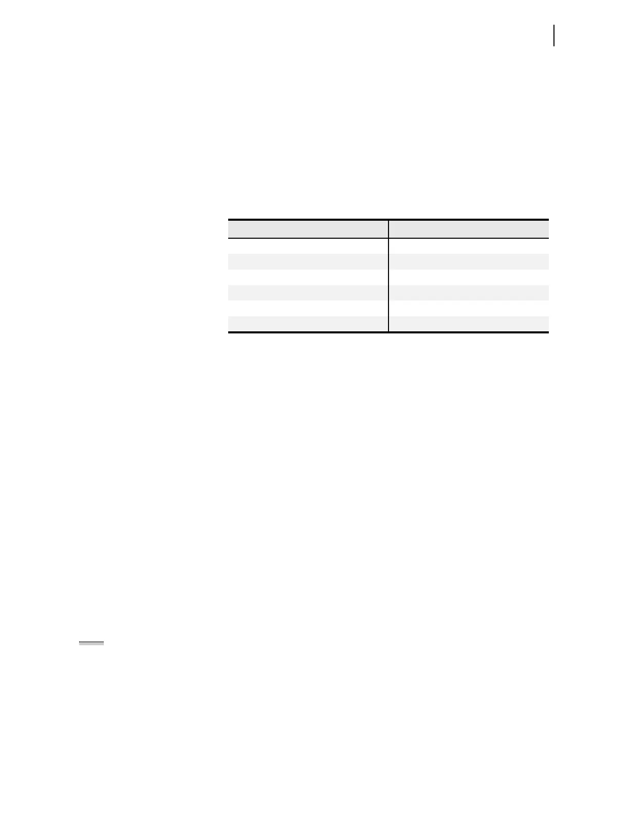
Typical ambient light levels are shown in Table 4.75. It is easy to see, that the
arc-flash event significantly exceeds virtually all illumination levels normally
found in a substation environment. The only exception is exposure to direct
sunlight, which can easily reach or exceed arc-flash TOL element setting
thresholds.
TOL Pickup is typically set based on the ambient light level. Ambient light is
continuously measured and can be easily displayed by using the front-panel
METER > Light Intensity menu as well as MET L command. Set the TOL
pickup to the lowest possible light intensity level but greater than the highest-
expected ambient light intensity level at each light-sensor installation.
Arc-flash protection, in general, requires both the measuring of an overcurrent
(50PAF) and the detection of light (TOLn). The output logic should in most
cases be the AND of the 50PAF and TOLn outputs. In applications where
intermittent loss of load can be tolerated (noncritical loads), it may be
desirable to operate without overcurrent element supervision
(OUTxxx := TOLn), relying only on the light detection element instead of
having the overcurrent element (50PAF) supervise the light element (TOLn) in
the output logic (OUTxxx := 50PAF AND TOLn). This approach offers
fastest tripping times, but is less secure (can be tripped with the light input
only).
Output Logic Programming
As stated earlier, arc-flash protection involves detecting an overcurrent as well
as light (arc). Location of the light sensors and source(s) of the arc energy
must also be considered in developing the trip output logic. If the relay detects
both signals simultaneously, it is desirable to trip the “source breaker(s).”
The Relay Word bits for arc-flash protection (see Figure 4.102 and
Figure 4.103) are: 50PAF, 50NAF, TOL1, TOL2, TOL3, TOL4, TOL5, TOL6,
TOL7 and TOL8.
As described earlier, you select two output contacts for high-speed processing
by setting AOUTSLOT appropriately. You should use the high-speed contact,
instead of the default OUT103 shown in Ta ble 4.65, for arc-flash tripping.
Also to ensure all the advantages of the trip logic (trip seal-in, event report
trigger, etc.) the arc-flash trip should be included in the trip equation TR (see
Table 4.52 and Figure 4.44 for detail).
To get additional speed, select the fast hybrid output option card (4DI/4DO).
This card contains trip duty rated solid state output contacts, which operate
within 50 µs (as much as 8 ms faster than the standard electromechanical
outputs).
Table 4.75 Typical Ambient Illumination Light Levels
Light Level Example
50 lux Living room
80 lux Brightly lit room
500 lux Brightly lit office
1,000 lux TV studio
> 20,000 lux Direct sunlight
20,000 to >1,000,000 lux Arc-flash event
a
a
A. D. Stokes, D. K. Sweeting, “Electric Arc Burn Hazards”, IEEE Transactions on industry
applications, Vol. 42, No. 1. January/February 2006.
NOTE: When using fast hybrid
output contacts, do not use the
FAILSAFE mode for those outputs.