4.44
SEL-751 Relay Instruction Manual Date Code 20170927
Protection and Logic Functions
Group Settings (SET Command)
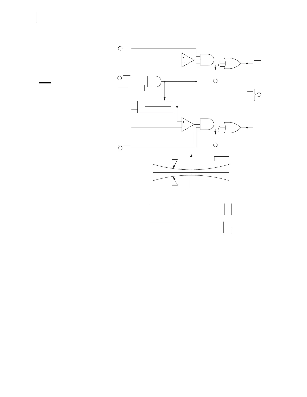
q From Figure 4.29 and Figure 4.30; w to Figure 4.32 and Figure 4.33;
e from Figure 4.25.
Figure 4.31 Zero-Sequence Voltage-Polarized Directional Element
(Ungrounded/High-Impedance Grounded Systems)
The 3V0 input to Figure 4.31 may be either a calculated value (when
VSCONN := VS and DELTA_Y := WYE) or a measured value (when
VSCONN := 3V0). See Zero-Sequence Voltage Sources on page 4.33.
I
N
3V
0
Z0F = —0.10, Forward Threshold = 0.75 • Z0F — 0.25 •
Forward Threshold:
I
N
3V
0
Z0R = 0.10, Reverse Threshold = 0.75 • Z0R + 0.25 •
Reverse Threshold:
Note: 1 ∠–90° = One Ohm at —90° Angle
For setting ORDER = U, settings Z0F and Z0R are set internally, as shown above, and hidden.
Direction Element Characteristics
R0
X0
Forward Threshold
Reverse Threshold
Z0 PLANE
RDIRN
FDIRN
Forward
Reverse
ORDER = U
50NF
Enable
Forward
Threshold
DIRNE
Reverse
Threshold
50NR
Re[3V
0
•(I
N
•1 ∠–90°)*]
|I
N
|
2
Z0 =
I
N
3V
0
Relay
Word
Bits
Relay
Word
Bit
Relay
Word
Bit
Relay
Word
Bit
"Forward"
Outputs
"Reverse"
Outputs
Setting
3
3
3
1
2
1
NOTE: Residual ground current I
G
is
used in place of neutral current I
N
under certain conditions. See Switch
Between I
N
and I
G
for Low-Impedance
Grounded and Ungrounded/High-
Impedance Grounded Systems on
page 4.31