2.49
Date Code 20170927 Instruction Manual SEL-751 Relay
Installation
Arc-Flash Protection: System Installation
Splice connectors can be added for the arc-flash fiber sensors to meet the
shipping needs for large switchgears that require multiple splits for transpor-
tation. For multimode fiber-optic arc-flash detection sensors with additional
splice connectors, refer to the SEL-C814 Arc-Flash Detection (AFD) Fiber
Cables and Accessories MOT.
Ordering Examples Using the SEL-C814 Model Option Table
This example of a bare-fiber sensor with four ST connectors and an A
dimension of 15 meters, as shown in Figure 2.47, shows the part numbers
generated using an SEL-C814 MOT and the link optical loss calculations.Two
connectors is the standard configuration.
Figure 2.47 Bare-Fiber Sensor Assembly With Two Additional ST Splice
Connectors
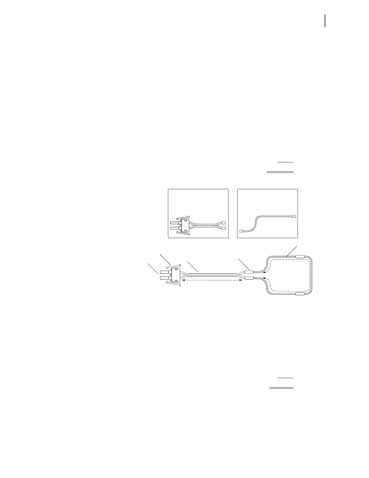
This example of a point sensor with two V-pin connectors, as shown in
Figure 2.48, shows the part numbers generated using a C814 MOT and the
link optical loss calculations.
Link Budget 17 dB
– (2 dB x # of connector splices) –8 dB
– (0.175 dB x A dimension x 2) –5.25 dB
Link Losses = available for B meters 3.75 dB
÷ (0.175 dB/m) 21.42 meters
maximum B dimension
Link Budget 12.25 dB
– (2 dB x # of connector splices) –4 dB
Link Losses = available for A meters 8.25 dB
÷ (2 x 0.175 dB/m) 23.6 meters
maximum A dimension
B Meters
A Meters
P/N C814CSS007
P/N C814CSS007
P/N C814CSS007
Note: To complete the fiber assembly, you will also need to
order two ST Connector Splice bushings with P/N 915900151
ST-ST Connector
Terminated Clear-Jacketed
Fiber, Simplex Cable
P/N C814CSS007
Dual V-Pin Latch-V-Pin
Terminated Black-Jacketed
Fiber, Zipcord Duplex Cable
P/N C814BSL015
Black-Jacketed
Fiber Zipcord
Duplex
V-Pin
Terminators
Dual V-Pin
Latch
ST Connector
Splices
Clear-Jacketed Fiber