2.43
Date Code 20170927 Instruction Manual SEL-751 Relay
Installation
Arc-Flash Protection: System Installation
clearance and creepage requirements. Sensors should be permanently affixed
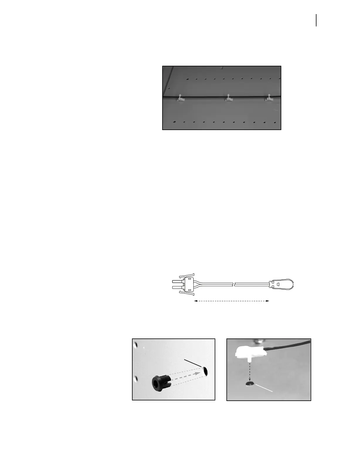
through the use of supplied mounting grommets or permanent cable ties.
Figure 2.34 shows an example of a typical black-jacketed fiber installation.
Figure 2.34 Black-Jacketed Fiber installation Example
Fiber-bending radius must be kept greater than 50 mm (2 in). Care should be
exercised when crossing from a moving part (such as control cabinet door) to
a stationary switchgear enclosure. Use standard wiring practices with bundled
fibers and well-defined strain relief points. Additional attention is necessary
to prevent moving parts, such as a breaker truck assembly, from inadvertently
damaging the arc-flash sensor fibers. Although easily detected by the sensor
diagnostics, such problems can be eliminated through careful installation
planning. Once routed, fiber sensors are connected to the SEL-751 as shown
in Figure 2.33.
Point-Sensor
Installation
The point-sensor is optimized for monitoring confined switchgear spaces
where the distance between sensors and the potential sources of arc (ener-
gized parts) can be kept below 2 m. Such spaces typically include breaker
compartments, outgoing and incoming cable compartments, and potential
transformer (PT) compartments. Figure 2.35 shows a schematic diagram of
the point-sensor assembly.
Figure 2.35 Point-Sensor Assembly
The sensor is mounted flush on the switchgear cabinet wall, using a standard
1/4-inch hole. Mounting steps are shown in Figure 2.36.
Figure 2.36 Point-Sensor Installation
1. Mounting Grommet Insertion
(1/4” diameter hole)
2. Sensor Insertion
(1/4” diameter hole)
Black-Jacketed Fiber Zipcord Duplex
V-Pin
Terminators
Dual V-Pin
Latch
Sensors
1–35 Meters