4.126
SEL-751 Relay Instruction Manual Date Code 20170927
Protection and Logic Functions
Group Settings (SET Command)
Set 81Rn Trend to INC or DEC to limit operation of the element to increasing
or decreasing frequency respectively. Also, when set to INC or DEC the ele-
ment is supervised by nominal frequency, FNOM. Set the trend to ABS if you
want the element to disregard the frequency trend.
Voltage and current supervision: A minimum positive-sequence voltage and/
or current is necessary for the operation of the 81R element when the levels
are specified by the 81RISUP and 81RVSUP settings, respectively. Set
81RISUP := OFF if no current supervision is necessary and similarly
81RVSUP := OFF if no voltage supervision is necessary. In any case, the ele-
ment is also supervised by Relay Word FREQTRK, which ensures that the
relay is tracking and measuring the system frequency.
Use the Relay Word bit 81RnT to operate output contacts to open appropriate
breaker(s) as necessary for your load-shedding scheme.
Fast Rate-of-Change-
of-Frequency (81RF)
Protection
The fast rate-of-change-of-frequency protection, 81RF, provides a faster
response compared to the frequency (81) and rate-of-change-of-frequency
(81R) elements. The fast operating speed makes the 81RF element suitable for
detecting islanding conditions.
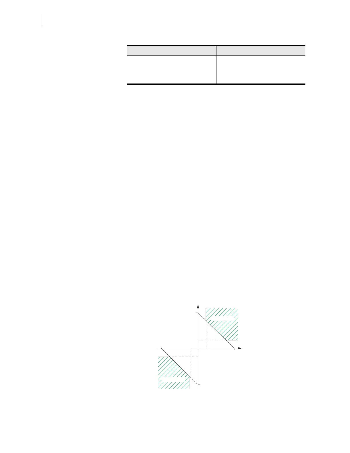
The element uses a characteristic (see Figure 4.77) based on frequency deviation
from nominal frequency (DF = FREQ – FNOM) and rate-of-change-of-fre-
quency (DF3C) to detect islanding conditions. The element uses a time win-
dow of three cycles to calculate the value of DF3C. Under steady-state
conditions, the operating point is close to the origin. During islanding condi-
tions, depending on the accelerating or decelerating of the islanded system,
the operating point enters Trip Region 1 or Trip Region 2 of the characteristic.
The elements uses the settings 81RFDFP in Hz and 81RFRP in Hz/s to config-
ure the characteristic (see Table 4.51).
Figure 4.77 81RF Characteristics
0.32–0.29 24
0.28–0.26 27
< 0.25 30
Table 4.50 Time Window Versus 81RnTP Setting (Sheet 2 of 2)
81RnTP Setting (Hz/sec) Time Window (Cycles)
DF3C Hz/s
(df/dt calculated over 3-cycle window)
0.2
—0.2
0.1
—0.1
Trip Region 2
Trip Region 1
DF (FREQ-FNOM) Hz
+81RFDFP
+81RFRP
—81RFDFP
—81RFRP