4.28
SEL-751 Relay Instruction Manual Date Code 20170927
Protection and Logic Functions
Group Settings (SET Command)
q Figure 4.25; w Figure 4.31; e Figure 4.32; r Figure 4.33; t Figure 4.34; y Figure 4.35; u Residual Time-
Overcurrent Elements 51G1T and 51G2T;
i Figure 4.2; o Figure 4.8; a Figure 4.9.
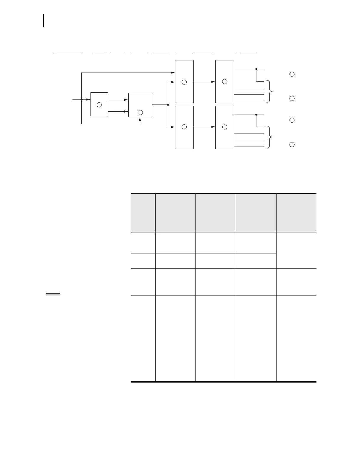
Figure 4.21 General Logic Flow of Directional Control for Neutral Ground and Residual Ground Overcurrent
Elements (Ungrounded/High-Impedance Grounded Systems; ORDER := U)
FDIRN/
RDIRN
DIRNE
ORDER = U
50NF/
50NR
to Neutral Ground
Time-Overcurrent
Elements
to Neutral Ground
Inst./Def.-Time
Overcurrent Elements
Level 1 N1DIR
DIRNF/
DIRNR
Ungrounded/
High-Impedance
DIRGF/
DIRGR
Level 1 G1DIR
Level 2 G2DIR
Level 3 G3DIR
Level 4 G4DIR
to Residual Ground
Inst./Def.-Time
Overcurrent Elements
Level 2 N2DIR
Level 3 N3DIR
Level 4 N4DIR
to Residual Ground
Time-Overcurrent
Elements
Enable Directional
Elements with Setting
ORDER
Internal
Enables
Relay
Word Bit
Outputs
Directional
Elements
Relay
Word Bit
Outputs
Relay
Word Bit
Outputs
Direction
Forward/
Reverse Logic
Directional
Control
Directional
Element
Routing
1
2
3
4
5
6
7
8
8
9
Table 4.19 Available Ground Directional Elements
ORDER
Setting
Choices
Corresponding
Ground
Directional
Element (and
System
Grounding)
Corresponding
Internal
Enables (and
System
Grounding)
Corresponding
Figures
Availability
Q Negative-
sequence
voltage-polarized
DIRQGE Figure 4.23,
Figure 4.26
All models (not
dependent on
neutral channel
[IN])
V Zero-sequence
voltage-polarized
DIRVE Figure 4.24,
Figure 4.27
I Channel IN
current polarized
DIRIE Figure 2.25,
Figure 4.24,
Figure 4.28
Models with a
1A or 5 A
nominal neutral
channel (IN)
S
a
a
S, P, and U are mutually exclusive—they cannot be listed together in the ORDER setting.
Zero-sequence
voltage-polar-
ized (Low-
impedance)
DIRNE (Low-
impedance)
Figure 2.28,
Figure 4.25,
Figure 4.29
Models with a
0.2 A nominal
neutral channel
(IN)
P
a
Wattmetric and
incremental
conductance
(Petersen coil)
DIRNE
(Petersen coil)
Figure 2.30,
Figure 4.25,
Figure 4.30
U
a
Zero-sequence
voltage-
polarized
(Ungrounded/
high-impedance)
DIRNE
(Ungrounded/
high-impedance)
Figure 2.28,
Figure 2.29,
Figure 2.31,
Figure 4.25,
Figure 4.31
NOTE: The neutral channel (IN) can
also be ordered as a 0.2 A nominal
neutral channel without directional
option for use as nondirectional
sensitive earth fault (SEF) protection.