D.23
Date Code 20170927 Instruction Manual SEL-751 Relay
DNP3 Communications
DNP3 Documentation
The SEL-751 also supports Pattern Control Blocks (Object 12, Variations
2 and 3) to control multiple binary output points. Variation 2 defines the
control type (Trip/Close, Set/Clear, or Pulse) and the range of points to
operate. Variation 3 provides a pattern mask that indicates which points in that
range should be operated. Object 12, Variations 2 and 3 define the entire
control command: the DNP3 master must send both for a successful control.
For example, the DNP3 master sends an Object 12, Variation 2 message to
request a Trip of the range of indices 0–7. The DNP3 master then sends an
Object 12, Variation 3 message with a hexadecimal value of “BB” as the
pattern mask (converted to binary notation: 10111011). Read right to left in
increasing bit order, the Pattern Block Control command results in a TRIP of
indexes 0, 1, 3 to 5, and 7. Multiple binary output point control operations are
not guaranteed to occur during the same processing interval.
Control Point
Operation
Use the Trip and Close, Latch On/Off and Pulse On operations with Object 12
control relay output block command messages to operate the points shown in
Table D.13. Pulse operations provide a pulse with duration of one protection
processing interval. When setting EN_LRC := Y (see Table 9. 4 ), the Relay
Word bit LOCAL supervises the CC and OC bits. If the LOCAL bit is asserted
(LOCAL = 1), the relay does not set the CC or OC bits. The Relay Word bit
LOCAL is determined by the LOCAL SEL
OGIC control equation (see
Table 9.4).
Analog Inputs
Analog Inputs (30) and Analog Change Events (32) are supported as defined
in Table D.11. The DVARAI1 (DVARAIn for DNP3 LAN/WAN session n)
setting defines the default variation for both static and event inputs. Only the
Read function code (1) is allowed with these objects. Unless otherwise
indicated, analog values are reported in primary units. See Appendix L:
Analog Quantities for a list of all available analog inputs.
For all currents, the default scaling is the DECPLA setting on magnitudes and
scale factor of 100 on angles. The default dead band for currents is ANADBV
on magnitudes and ANADBM on angles. For all voltages, the default scaling
is the DECPLV setting on magnitudes and scale factor of 100 on angles. The
default dead band for voltages is ANADBV on magnitudes and ANADBM on
angles. For all Powers and Energies, the default scaling is the DECPLM
setting and default dead band is ANADBM. For all other quantities, the
default scaling is 1 and default dead band is ANADBM.
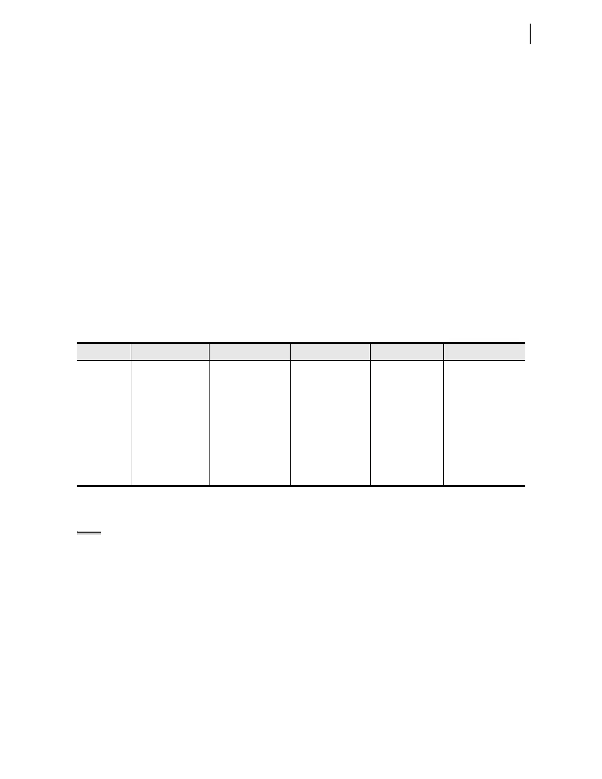
Table D.12 SEL-751 Object 12 Control Operations
Label Close/Pulse On Trip/Pulse On Nul/Latch On Nul/Latch Off Nul/Pulse On
RB01–RB32 Pulse Remote Bit
RB01–RB32
Pulse Remote Bit
RB01–RB32
Set Remote Bit
RB01–RB32
Clear Remote Bit
RB01–RB32
Pulse Remote Bit
RB01–RB32
RBxx:RByy Pulse RByy
RB01–RB32
Pulse RBxx
RB01–RB32
Pulse RByy
RB01–RB32
Pulse RBxx
RB01–RB32
Not Supported
OC Open Circuit
Breaker (Pulse OC)
Open Circuit Breaker
(Pulse OC)
Open Circuit Breaker
(Pulse OC)
No action Open Circuit Breaker
(Pulse OC)
CC Close Circuit
Breaker (Pulse CC)
Close Circuit Breaker
(Pulse CC)
Close Circuit
Breaker (Pulse CC)
No action Close Circuit Breaker
(Pulse CC)
OC:CC Close Circuit
Breaker (Pulse CC)
Open Circuit Breaker
(Pulse OC)
Close Circuit
Breaker (Pulse CC)
Open Circuit
Breaker (Pulse OC)
Not Supported
NOTE: Dead-band changes via
Object 34 are not stored in
nonvolatile memory. Make sure to
reissue the Object 34 dead-band
changes you want to retain after a
change to DNP port settings, issuing
a STA C command, or a relay cold-start
(power-cycle).