4.184
SEL-751 Relay Instruction Manual Date Code 20170927
Protection and Logic Functions
Global Settings (SET G Command)
Analog Outputs
If an SEL-751 configuration includes the four analog inputs and four analog
outputs (4 AI/4 AO) card, the analog outputs are allocated to output numbers 1-4.
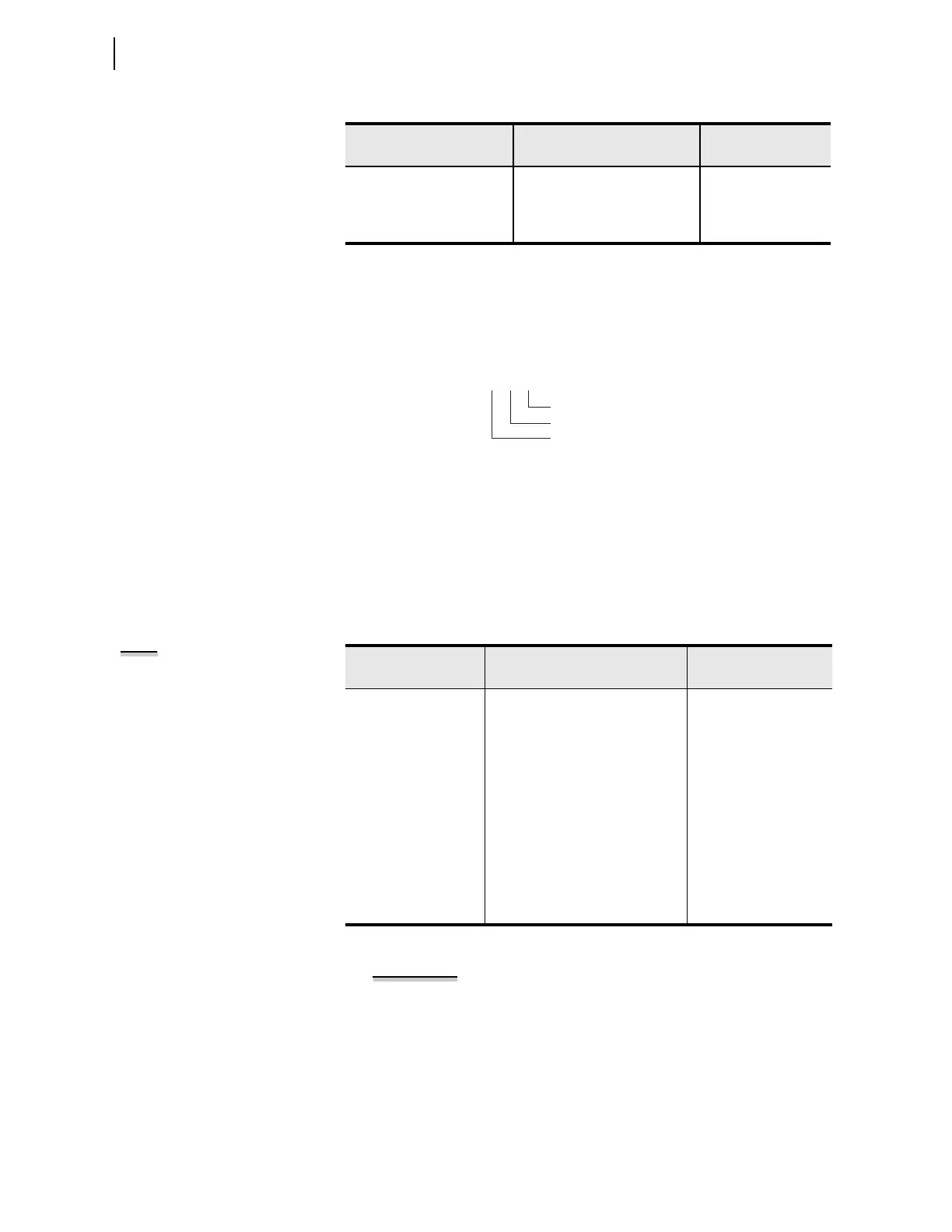
Figure 4.107 shows the x and y variable allocation for the analog output card.
Figure 4.107 Analog Output Number Allocation
For an analog input/output card in Slot 3, setting AO301AQ identifies the analog
quantity we assign to Analog Output 1 (when set to OFF, the device hides all associ-
ated AOx0y settings and no value appears on the output). You can assign any
of the analog quantities listed in Appendix L: Analog Quantities.
Table 4.78 shows the setting prompt, setting range, and factory-default
settings for an analog card in Slot 3.
EXAMPLE 4.38 Analog Quantity IA_MAG, A-Phase Current
Magnitude in Primary Amperes (0 to 3000 A Range), Using a -20 to
+20 mA Analog Output Channel
In this example, assume we want to display in the control room the analog
quantity (refer to
Appendix L: Analog Quantities
) IA_MAG, A-Phase current
magnitude in primary amperes (0 to 3000 A range), using a -20 to +20 mA
analog output channel. We install an analog input/output card in Slot C
(SEL
ECT 4 AI/ 4 AO) and set the card channel AO301, as shown in
Figure 4.108
. Note that the AO301 channel has to be configured as a
“current analog output” channel (refer to
Figure 2.4
through
Figure 2.6
).
AI301 HI WARN 1 OFF, –99999.000 to +99999.000 AI301HW1 := OFF
AI301 HI WARN 2 OFF, –99999.000 to +99999.000 AI301HW2 := OFF
AI301 HI ALARM OFF, –99999.000 to +99999.000 AI301HAL := OFF
a
Voltage setting range for a voltage transducer, i.e., when AI301TYP := V.
Table 4.77 Analog Input Card Settings in Slot 3 (Sheet 2 of 2)
Setting Prompt Setting Range
Setting Name :=
Fac to ry Defa ult
Table 4.78 Analog Output Card Settings in Slot 3
Setting Prompt Setting Range
Setting Name :=
Fac to ry De fa ult
AO301 ANALOG QTY Off, 1 analog quantity AO301AQ := OFF
AO301 TYPE I, V AO301TYP := I
AO301 AQTY LO –2147483647.000 to
+2147483647.000
AO301AQL := 4.000
AO301 AQTY HI –2147483647.000 to
+2147483647.000
AO301AQH := 20.000
AO301 LO OUT VAL –20.480 to +20.480 mA AO301L := 4.000
AO301 HI OUT VAL –20.480 to +20.480 mA AO301H := 20.000
AO301 LO OUT VAL –10.240 to +10.240 V AO301L := 0.000
a
a
Voltage setting range for a voltage transducer, i.e., when AO301TYP := V.
AO301 HI OUT VAL –10.240 to +10.240 V AO301H := 10.000
a
Output Number (1 through 4)
Slot Position (3 through 5)
Analog Output
AOx0y
NOTE: The SEL-751 hides the
following settings with default values
when you use a 3 DI/4 DO/1 AO card:
AOxx1TYP := I
AOxx1L := 4.000
AOxx1H := 20.000