9.11
Date Code 20170927 Instruction Manual SEL-751 Relay
Bay Control
Overview
Descriptions of the different menus, panes, and information in Bay Screen
Builder are as follows:
q
Project Screens Pane: Displays the names of the screens (as many
as 5) present in a project. Click a screen name to open the screen, and
double-click or right-click a screen name to access additional options
for that screen.
w
Screen Area: Displays the selected project screen and its symbols.
Create a single-line diagram or a metering or status screen by dragging
and dropping symbols from the Symbols pane.
e
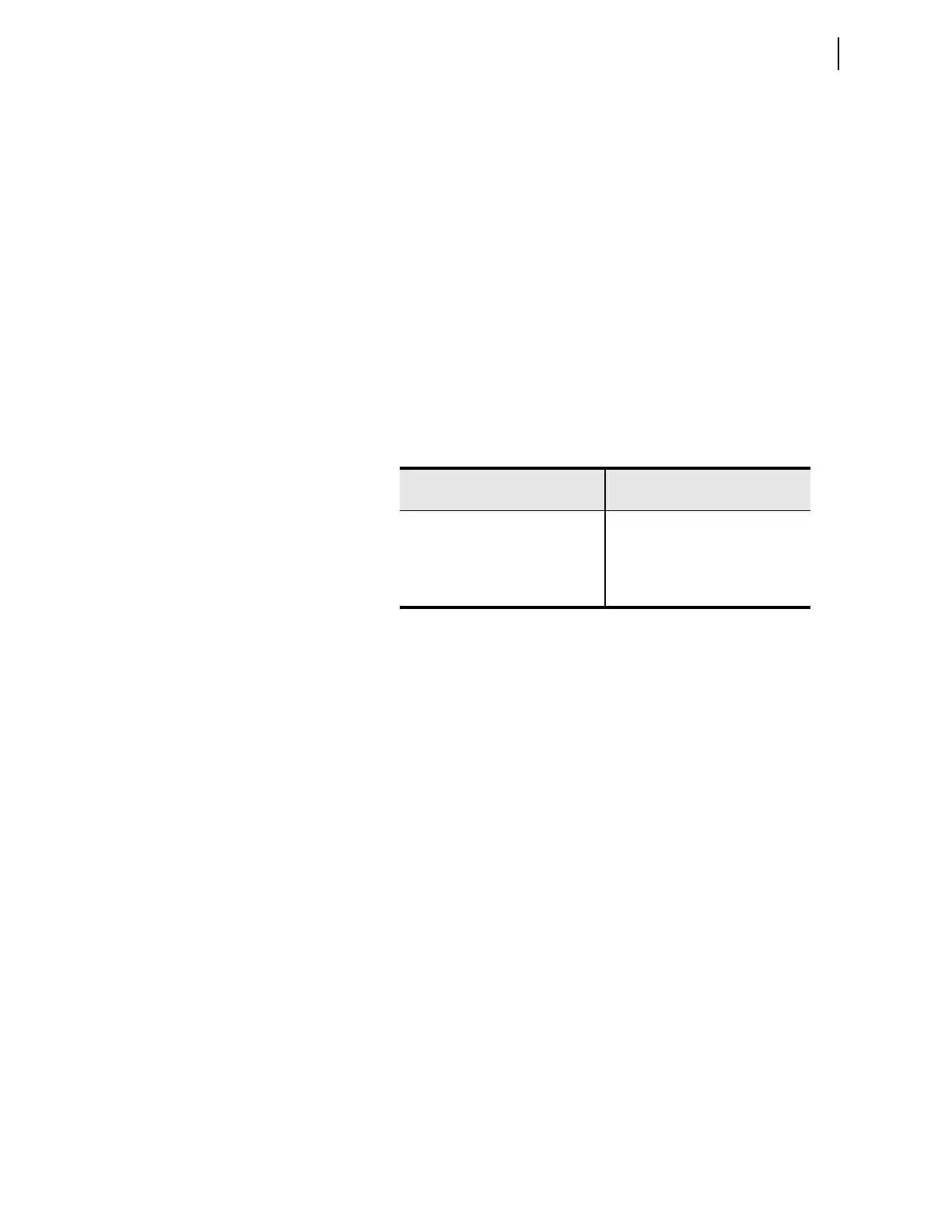
Symbols Pane: Displays the symbols available for selection. Bay
Screen Builder supports several static and a limited number of
dynamic ANSI and IEC symbols. Note that for a given project, you can
only use either ANSI or IEC symbols, not both. While there are no
constraints on the number of static symbols, Bay Screen Builder limits
the number of dynamic symbols. The following table provides the
number of breakers, disconnect switches, analog labels, and digital
labels supported in a given project.
r
Properties Pane: Displays the properties of a selected symbol. Edit
the symbol properties as needed for your application. For instance, the
breaker color sequence property identified in Table 9.1 can be set via
the appearance property of the breaker symbol (refer to Edit Symbol
Properties on page 9.16). Bay Screen Builder supports UTF-8
character encoding. Refer to the Product Literature CD for a complete
list of UTF-8 characters that can be rendered on the touchscreen
display.
t
Product Type: Displays the name of the QuickSet driver version of
the product associated with the selected project (e.g., SEL-751 007, as
shown in Figure 9.7). Select the product type in Bay Screen Builder
when you create a new project independent of QuickSet. View
Product Type though Settings > Project Settings. If a project is
edited via QuickSet, Bay Screen Builder inherits the product type from
the QuickSet settings file.
y
Project Symbol Type: Displays the symbol type (IEC or ANSI)
associated with the selected project as shown in Figure 9.7. Select the
symbol type when you create a new project. If a project is edited via
QuickSet, the ANSI symbol type is selected by default.
u
Auto Save: Provides a shortcut for changing the auto save setting for
the application. Enable Auto Save to allow Bay Screen Builder to
automatically save your project periodically. Your auto save setting
preference is saved when you exit the application and is applied the
next time you launch Bay Screen Builder. You can also set Auto Save
through Settings > Application Settings > File Handling.
Symbols
Number of Supported
Symbols per Project
Breakers 1
Disconnects 5
Analog Labels 32
Digital Labels 32