E.58
SEL-751 Relay Instruction Manual Date Code 20170927
Modbus RTU Communications
Communications Protocol
Trip/Warn Data
The Trip and Warn Status registers bits are “sticky” (once set, they are not cleared until target reset is issued from any interface) when
a trip event occurs.
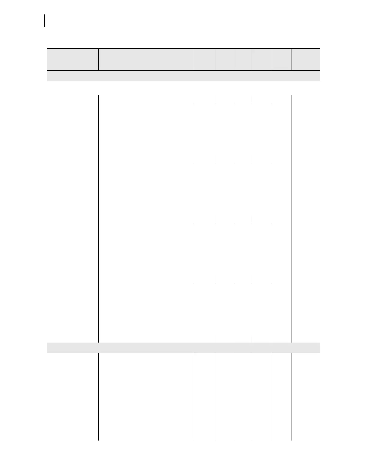
1730 (R) TRIP STATUS LO 0 65535 0 1 1830
Bit 0 = PHASE A1 50
Bit 1 = PHASE B1 50
Bit 2 = PHASE C1 50
Bit 3 = PHASE 50P1
Bit 4 = GROUND 50G1
Bit 5 = NEUTRAL 50N1
Bit 6 = NEG SEQ 50Q1
Bit 7 = PHASE A 51
Bit 8 = PHASE B 51
Bit 9 = PHASE C 51
Bit 10 = PHASE 51P1
Bit 11 = GROUND 51G1
Bit 12 = NEUTRAL 51N1
Bit 13 = NEG SEQ 51Q
Bit 14 = UNDERVOLT 27P1
Bit 15 = OVERVOLT 59P1
1731 (R) TRIP STATUS HI 0 65535 0 1 1831
Bit 0 = POWER FACTOR 55
Bit 1 = FREQUENCY 81D1
Bit 2 = FREQUENCY 81D2
Bit 3 = RTD-OTHER
Bit 4 = RTD-AMBIENT
Bit 5 = RTD-WIND BEAR
Bit 6 = RTD ERROR
Bit 7 = POWER ELEMENTS
Bit 8 = COMM IDLE
Bit 9 = COMM LOSS
Bit 10 = REMOTE TRIP
Bit 11 = COMM FAULT
Bit 12 = CONFIG FAULT
Bit 13 = RESERVED
Bit 14 = RESERVED
Bit 15 = BREAKER FAIL
1732 (R) WARN STATUS LO 0 65535 0 1 1832
Bit 0 = PHASE 50P2
Bit 1 = PHASE 50P3
Bit 2 = PHASE 50P4
Bit 3 = GROUND 50G2
Bit 4 = GROUND 50G3
Bit 5 = GROUND 50G4
Bit 6 = NEUTRAL 50N2
Bit 7 = NEUTRAL 50N3
Bit 8 = NEUTRAL 50N4
Bit 9 = NEG SEQ 50Q2
Bit 10 = NEG SEQ 50Q3
Bit 11 = NEG SEQ 50Q4
Bit 12 = PHASE 51P2
Bit 13 = GROUND 51G2
Bit 14 = NEUTRAL 51N2
Bit 15 = RESERVED
1733 (R) WARN STATUS HI 0 65535 0 1 1833
Bit 0 = POWER FACTOR 55
Bit 1 = SALARM
Bit 2 = WARNING
Bit 3 = RTD-WIND BEAR
Bit 4 = RTD-OTHER
Bit 5 = RTD-AMBIENT
Bit 6 = UNDERVOLT 27P2
Bit 7 = OVERVOLT 59P2
Bit 8 = FREQUENCY 81D3
Bit 9 = FREQUENCY 81D4
Bit 10 = RESERVED
Bit 11 = RESERVED
Bit 12 = RESERVED
Bit 13 = RESERVED
Bit 14 = RESERVED
Bit 15 = RESERVED
1734–1739 (R) Reserved
c
1834–1839
Relay Elements
1740 (R) NUM MSG RCVD 0 65535 0 1 1840
1741 (R) NUM OTHER MSG 0 65535 0 1 1841
1742 (R) INVALID ADDR 0 65535 0 1 1842
1743 (R) BAD CRC 0 65535 0 1 1843
1744 (R) UART ERROR 0 65535 0 1 1844
1745 (R) ILLEGAL FUNCTION 0 65535 0 1 1845
1746 (R) ILLEGAL REGISTER 0 65535 0 1 1846
1747 (R) ILLEGAL WRITE 0 65535 0 1 1847
1748 (R) BAD PKT FORMAT 0 65535 0 1 1848
1749 (R) BAD PKT LENGTH 0 65535 0 1 1849
1750–1759 (R) Reserved
c
1850–1859
Table E.34 Modbus Register Map
a
(Sheet 34 of 38)
Modbus Register
Address
b
Name/Enums Units Min Max Default
Scale
Fac to r
DeviceNet
Parameter
Numbers