6/02
7-3
DC1632/2240
Plug/Jack Locations
Wiring Data
Prelaunch Training/Review
Plug/Jack Locations
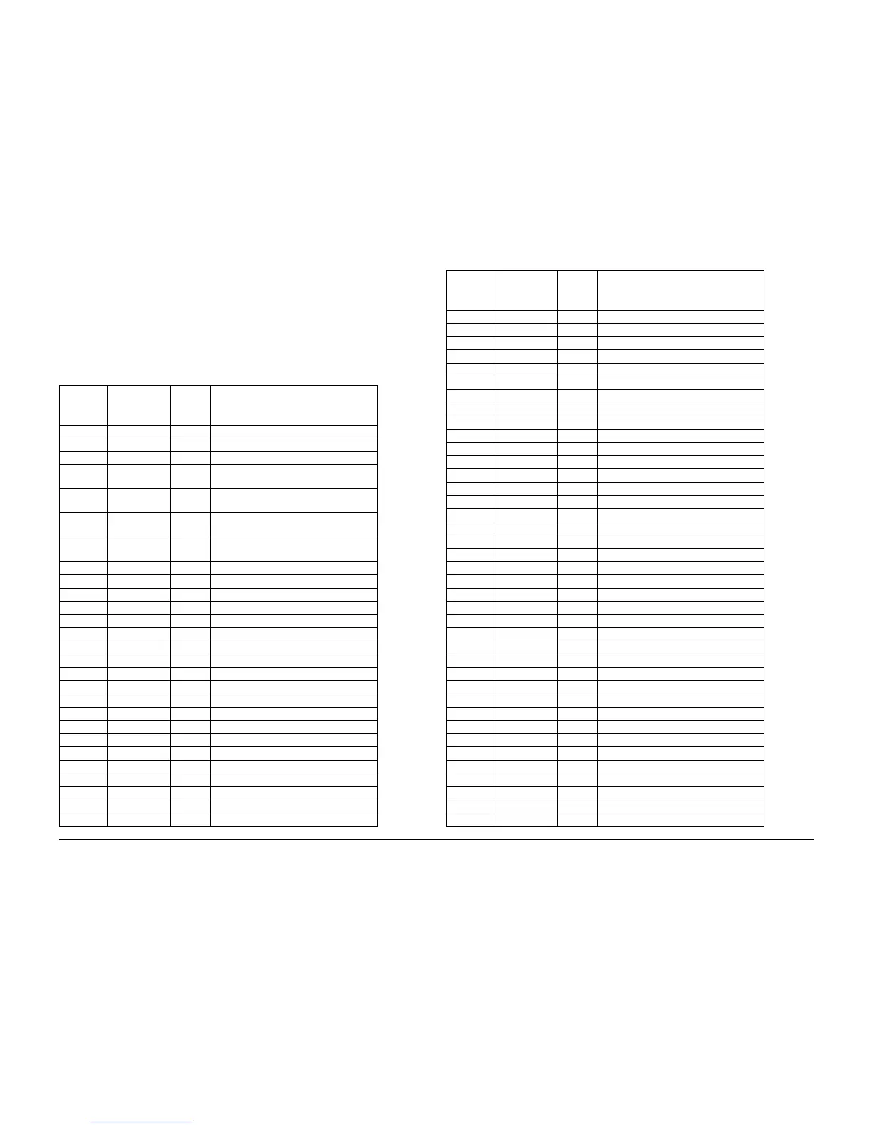
How to use the Plug/Jack Location List
The Plug/Jack Location List below is provided to locate plugs, jacks, or other terminating
devices. Locate the desired termination device in the first column (Plug/Jack Number) of the
list. Refer to the second column (Figure Number) to determine the figure number of the electri-
cal termination device. Refer to the (Item Number) column to determine the item number in the
adjacent Figure Number column. The fourth column supplies the title of the Figure.
Table 1 Plug / Jack Location List
Plug /
Jack
Number
Figure
Number
Item
Number Figure Title
2 Figure 12 8 HVPS T5, T7, +24V LVPS
15A Figure 16 19 I/F PWB, MAIN Motor, LVPS T2
16 Figure 16 16 I/F PWB, MAIN Motor, LVPS T2
42 Figure 18 10 AC Drive PWB, Noise Filter PWB, Delay
PWB
43 Figure 18 11 AC Drive PWB, Noise Filter PWB, Delay
PWB
46 Figure 18 1 AC Drive PWB, Noise Filter PWB, Delay
PWB
J70 Figure 18 12 AC Drive PWB, Noise Filter PWB, Delay
PWB
72 Figure 12 9 HVPS T5, T7, +24V LVPS
102 Figure 3 1 Inverter Transport Assembly
103 Figure 8 4 MSI Unit
104 Figure 7 3 Exit Transport Assembly
106 Figure 19 3 Left Lower Assembly, Tray 1 Feeder
108 Figure 19 2 Left Lower Assembly, Tray 1 Feeder
109 Figure 5 4 Registration Transport Assembly
111 Figure 3 14 Inverter Transport Assembly
113 Figure 3 8 Inverter Transport Assembly
115 Figure 17 10 Developer Motor, Tray 1 Size Switch
116 Figure 2 3 MOB Sensor Assembly
117 Figure 2 1 MOB Sensor Assembly
119 Figure 11 5 IBT Belt Assembly
121 Figure 11 4 IBT Belt Assembly
122 Figure 11 2 IBT Belt Assembly
125 Figure 19 7 Left Lower Assembly, Tray 1 Feeder
129 Figure 1 10 Xerographic
130 Figure 1 9 Xerographic
131 Figure 1 7 Xerographic
132 Figure 1 5 Xerographic
133 Figure 1 16 Xerographic
135 Figure 4 5 Duplex Transport Assembly
136 Figure 4 6 Duplex Transport Assembly
140 Figure 3 12 Inverter Transport Assembly
144 Figure 2 2 MOB Sensor Assembly
150 Figure 19 4 Left Lower Assembly, Tray 1 Feeder
151 Figure 1 12 Xerographic
152 Figure 1 15 Xerographic
153 Figure 1 19 Xerographic
154 Figure 1 17 Xerographic
155 Figure 5 3 Registration Transport Assembly
163 Figure 9 11 Toner Dispense Motor, Main Switch
165 Figure 9 8 Toner Dispense Motor, Main Switch
171 Figure 1 4 Xerographic
172 Figure 7 2 Exit Transport Assembly
173 Figure 13 9 Outlet Panel Assembly, Fuser PWB
203 Figure 16 10 I/F PWB, MAIN Motor, LVPS T2
205 Figure 19 1 Left Lower Assembly, Tray 1 Feeder
207 Figure 1 11 Xerographic
208 Figure 16 24 I/F PWB, MAIN Motor, LVPS T2
210 Figure 16 22 I/F PWB, MAIN Motor, LVPS T2
211 Figure 6 8 Fuser Assembly
212 Figure 6 11 Fuser Assembly
214 Figure 12 11 HVPS T5, T7, +24V LVPS
215 Figure 3 5 Inverter Transport Assembly
216 Figure 3 15 Inverter Transport Assembly
217 Figure 3 4 Inverter Transport Assembly
218 Figure 3 2 Inverter Transport Assembly
219 Figure 3 3 Inverter Transport Assembly
220 Figure 7 4 Exit Transport Assembly
221 Figure 17 7 Developer Motor, Tray 1 Size Switch
222 Figure 7 1 Exit Transport Assembly
223 Figure 1 8 Xerographic
224 Figure 1 6 Xerographic
225 Figure 1 3 Xerographic
226 Figure 1 20 Xerographic
227 Figure 9 17 Toner Dispense Motor, Main Switch
228 Figure 9 12 Toner Dispense Motor, Main Switch
229 Figure 9 10 Toner Dispense Motor, Main Switch
Table 1 Plug / Jack Location List
Plug /
Jack
Number
Figure
Number
Item
Number Figure Title

 Loading...


