6/02
7-7
DC1632/2240
Plug/Jack Locations
Wiring Data
Prelaunch Training/Review
864 Figure 30 12 Tamper Unit, Staple Unit
865 Figure 30 14 Tamper Unit, Staple Unit
866 Figure 31 9 Finisher (rear) (1 0f 2)
867 Figure 31 2 Finisher (rear) (1 0f 2)
868 Figure 31 1 Finisher (rear) (1 0f 2)
869 Figure 31 12 Finisher (rear) (1 0f 2)
870 Figure 30 13 Tamper Unit, Staple Unit
871 Figure 30 16 Tamper Unit, Staple Unit
873 Figure 31 10 Finisher (rear) (1 0f 2)
874 Figure 30 1 Tamper Unit, Staple Unit
875 Figure 30 3 Tamper Unit, Staple Unit
876 Figure 30 2 Tamper Unit, Staple Unit
877 Figure 30 5 Tamper Unit, Staple Unit
878 Figure 30 4 Tamper Unit, Staple Unit
879 Figure 31 7 Finisher (rear) (1 0f 2)
880 Figure 31 5 Finisher (rear) (1 0f 2)
881 Figure 31 6 Finisher (rear) (1 0f 2)
882 Figure 31 11 Finisher (rear) (1 0f 2)
883 Figure 31 3 Finisher (rear) (1 0f 2)
884 Figure 31 4 Finisher (rear) (1 0f 2)
885 Figure 30 10 Tamper Unit, Staple Unit
886 Figure 30 8 Tamper Unit, Staple Unit
887 Figure 30 9 Tamper Unit, Staple Unit
888 Figure 30 15 Tamper Unit, Staple Unit
889 Figure 32 2 Finisher PWB
890 Figure 30 6 Tamper Unit, Staple Unit
891 Figure 30 17 Tamper Unit, Staple Unit
892 Figure 32 1 Finisher PWB
J903 Figure 12 13 HVPS T5, T7, +24V LVPS
J925 Figure 12 12 HVPS T5, T7, +24V LVPS
J4401 Figure 14 11 ESS assembly
J4500 Figure 14 9 ESS assembly
4510 Figure 14 10 ESS assembly
CN1 Figure 24 8 Control Panel
CN2 Figure 24 7 Control Panel
CN5 Figure 24 6 Control Panel
CN9 Figure 24 1 Control Panel
CN10 Figure 24 13 Control Panel
CN11 Figure 24 2 Control Panel
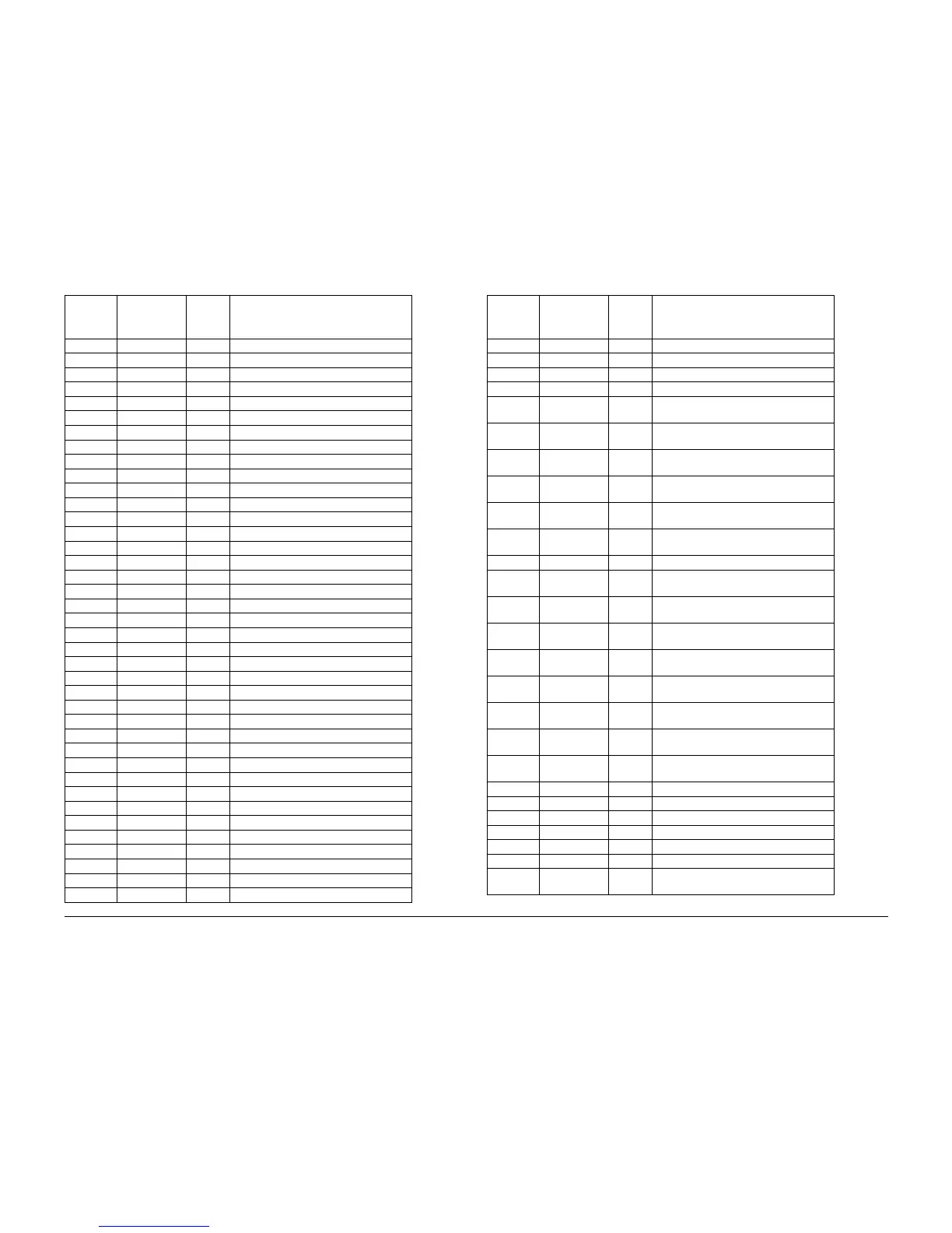
Table 1 Plug / Jack Location List
Plug /
Jack
Number
Figure
Number
Item
Number Figure Title
CN12 Figure 24 3 Control Panel
CN13 Figure 24 14 Control Panel
FS37 Figure 6 2 Fuser Assembly
FS38 Figure 6 1 Fuser Assembly
FS39 Figure 18 3 AC Drive PWB, Noise Filter PWB, Delay
PWB
FS40 Figure 18 2 AC Drive PWB, Noise Filter PWB, Delay
PWB
FS41 Figure 18 4 AC Drive PWB, Noise Filter PWB, Delay
PWB
FS45 Figure 18 9 AC Drive PWB, Noise Filter PWB, Delay
PWB
FS47 Figure 18 7 AC Drive PWB, Noise Filter PWB, Delay
PWB
FS48 Figure 18 8 AC Drive PWB, Noise Filter PWB, Delay
PWB
FS51 Figure 12 10 HVPS T5, T7, +24V LVPS
FS56 Figure 9 14 Toner Dispense Motor (Y,M,C,K), Main
Switch
FS57 Figure 9 13 Toner Dispense Motor (Y,M,C,K), Main
Switch
FS61 Figure 18 16 AC Drive PWB, Noise Filter PWB, Delay
PWB
FS62 Figure 18 15 AC Drive PWB, Noise Filter PWB, Delay
PWB
FS68 Figure 9 15 Toner Dispense Motor (Y,M,C,K), Main
Switch
FS69 Figure 9 16 Toner Dispense Motor (Y,M,C,K), Main
Switch
FS76 Figure 18 13 AC Drive PWB, Noise Filter PWB, Delay
PWB
FS77 Figure 18 17 AC Drive PWB, Noise Filter PWB, Delay
PWB
FS78 Figure 13 4 Outlet Panel Assembly, Fuser PWB
FS79 Figure 13 3 Outlet Panel Assembly, Fuser PWB
FS80 Figure 13 8 Outlet Panel Assembly, Fuser PWB
FS81 Figure 13 5 Outlet Panel Assembly, Fuser PWB
FS82 Figure 13 7 Outlet Panel Assembly, Fuser PWB
FS83 Figure 13 6 Outlet Panel Assembly, Fuser PWB
FS90 Figure 18 18 AC Drive PWB, Noise Filter PWB, Delay
PWB
Table 1 Plug / Jack Location List
Plug /
Jack
Number
Figure
Number
Item
Number Figure Title
 Loading...


