1 Numerical Input
10-12 WindO/I-NV4 User’s Manual
■ Reverse
Select this check box to reverse the text color and plate color during display mode when in entry mode.
Can only be set when Standard is selected for Image Type under the View tab.
■ Display Numerical Value with “*”
*3
Select this check box to display the entered value as * (asterisks).
Nothing is displayed if the value of device address is 0 when this check box is selected and the Suppress Zeros
check box is selected on the General tab. When this check box is selected in entry mode, nothing is displayed until a
value is entered from the key buttons or keypad. If ENT is pressed with nothing displayed, 0 is written to the
destination device address.
■ With Unit
*3
Select this check box to display units or other characters at the end of a number. Displayed characters must be
registered in Text Manager. The displayed text color will be as set for Text Color under the Format tab.
■ Windows Font
Configures the font to use as the Windows Font.
Select Windows for Font to display the current settings. To change the settings, click Change to display the Font
dialog box. For details, refer to Chapter 2 “Windows Font” on page 2-13.
■ Change Display Colors
*3
To switch the text and plate colors, select this check box and select the method to the display colors from the following.
*3 Advanced mode only
Text ID: Specifies the Text Manager ID No. (1 to 32000).
Click to display Text Manager.
Text: Displays the characters of the specified Text ID.
• The maximum number that can be displayed with this function is 4 characters. The fifth and subsequent
characters of a character string are not displayed. However, if using a Windows font for the selected text
ID, the fifth and subsequent characters of a character string will still be displayed.
• If a carriage return (CR) is included the characters after the CR are not displayed.
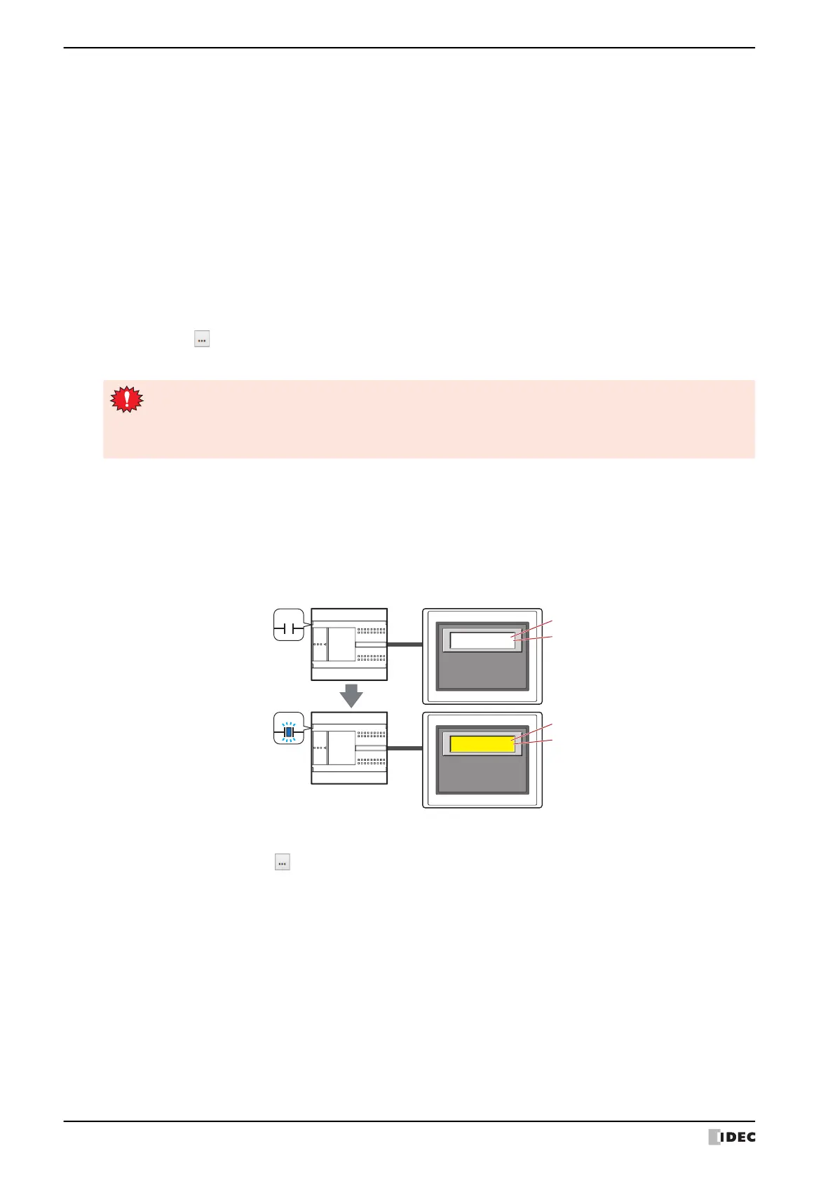
Trigger Device Address: Specifies the bit device or the bit number of the word device to use as the trigger to switch
the text and plate colors.
Click to display the Tag Editor. For the device address configuration procedure, refer to
Chapter 2 “5.1 Device Address Settings” on page 2-70.
When the value of device address is 0, the color specified in Text Color or in Plate Color
on the View tab will be displayed.
When the value of device address is 1, the color displayed and specified in Text Color or
Plate Color under the Change Display Colors.
Text Color: Selects the color (color: 256 colors, monochrome: 16 shades) of the text when switching.
Click this button to display the Color Palette. Select a color from the Color Palette.
Plate Color: Selects the plate color (color: 256 colors, monochrome: 16 shades) when switching.
Click this button to display the Color Palette. Select a color from the Color Palette.
This option can only be configured when Standard is selected for Image Type on the View tab.
MICRO/I
1234
1234
0
1
Trigger Device Address
Trigger Device Address
External device
Text Color
Plate Color on the View tab
Text Color under Change Display Colors
Plate Color under Change Display Colors
 Loading...