EasyManuals Logo

Lexmark X945e MFP 7510 series User Manual

Lexmark X945e MFP 7510 series
847 pages
To Next Page IconTo Next Page
To Previous Page IconTo Previous Page
Page #457 background imageLoading...
Page #457 background image
Repair information 4-25
7510
Go Back
Previous
Next
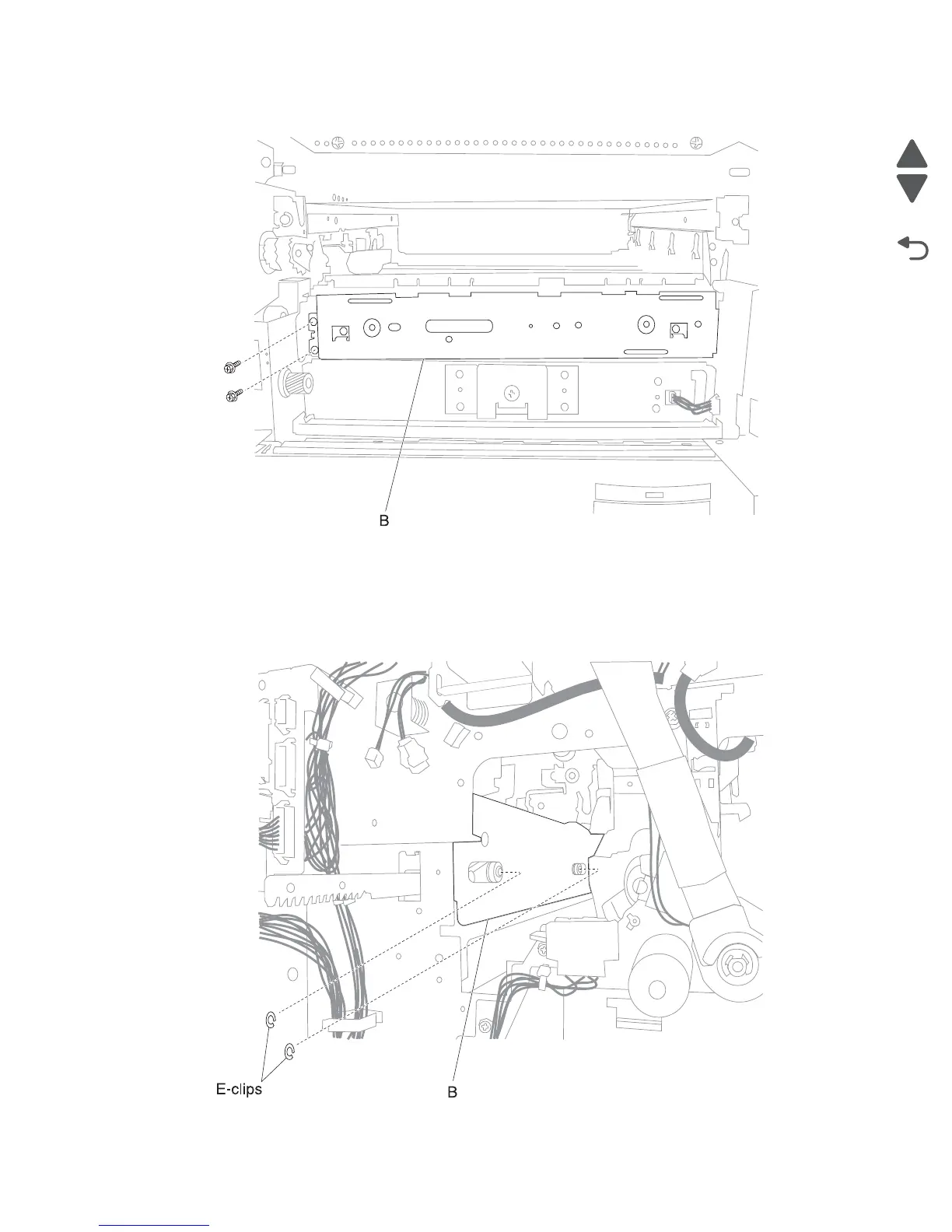
21. Remove the two screws from the left transfer belt lift assembly (B).
Note: In order to remove the left transfer belt lift assembly (B), two E-clips and two washers must be
removed. The two E-clips and two washers are located inside the machine in the area where the K PC unit
is located.
Warning: Do not loose the two E-clips, four washers, and two bearings. The need to be installed on the
new left transfer belt lift assembly (B) being installed in the machine.
22. Remove the two E-clips and the two washers securing the left transfer belt lift assembly (B) to the machine.

Table of Contents

Questions and Answers:

Question and Answer IconNeed help?

Do you have a question about the Lexmark X945e MFP 7510 series and is the answer not in the manual?

Lexmark X945e MFP 7510 series Specifications

General IconGeneral
BrandLexmark
ModelX945e MFP 7510 series
CategoryPrinter
LanguageEnglish

Related product manuals