4.153
Date Code 20170927 Instruction Manual SEL-751 Relay
Protection and Logic Functions
Group Settings (SET Command)
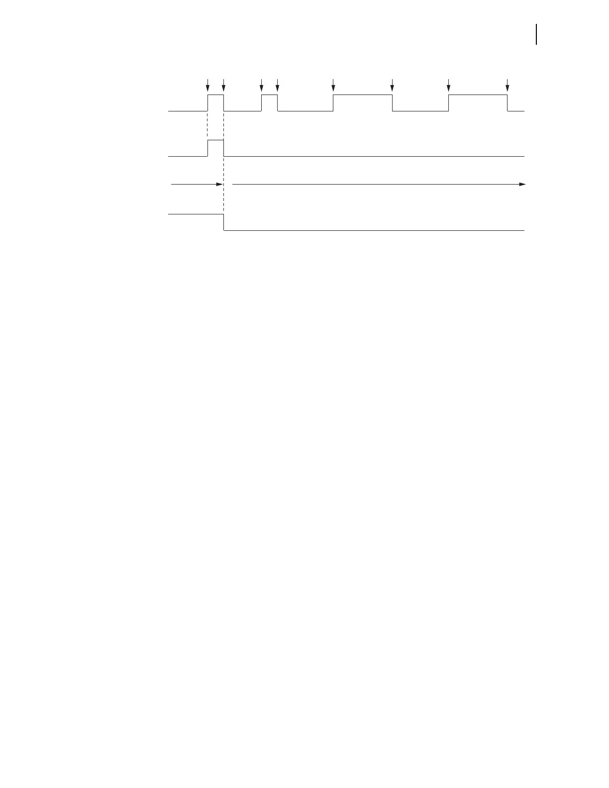
q Fault occurs beyond line recloser; w fault cleared by line recloser fast curve; e line recloser recloses into fault;
r fault cleared by line recloser slow curve.
Figure 4.89 Operation of SEL-751 Shot Counter for Sequence Coordination With Line Recloser (Additional
Settings Example 2)
The line recloser continues to operate for the permanent fault beyond it, but
the SEL-751 shot counter does not continue to increment. Sequence
coordination setting 79SEQ is effectively disabled by the shot counter
incrementing from shot = 0 to shot = 1.
79SEQ := 79RS AND 51P1P AND (logical 0) = Logical 0
The shot counter stays at shot = 1.
Thus, if there is a coincident fault between the SEL-751 and the line recloser,
the SEL-751 operates on 51AT, 51BT, or 51CT and then recloses once, instead
of going straight to the lockout state (shot = 1 < last shot = 2).
As stated earlier, the reset time setting 79RSD takes the shot counter back
to shot = 0 after a sequence coordination operation increments the shot
counter. Make sure that reset time setting 79RSD is set long enough to
maintain the shot counter at shot = 1 as shown in Figure 4.89.
Reclose Supervision Setting (79CLS)
See Reclose Supervision Logic on page 4.131.
Demand Metering
The SEL-751 provides demand and peak demand metering, selectable
between thermal and rolling demand types, for the following values:
➤ IA, IB, IC, phase currents (A primary)
➤ IG Residual ground current
(A primary; IG = 3I0 = IA + IB + IC)
➤ 3I2 Negative-sequence current (A primary)
Table 4.57 shows the demand metering settings. Also refer to Section 5:
Metering and Monitoring and Section 7: Communications for other related
information for the demand meter.
79SEQ = 79RS * 51P1 * SHO
51P1
Shot Counter
SH0
01
qw ew e r e
r