9.19
Date Code 20170927 Instruction Manual SEL-751 Relay
Bay Control
Bay Control Application Example
Enter QuickSet
Settings
The breaker, disconnect, analog and digital label, local/remote, and trip and
close settings that follow are the settings applicable to the single-line diagram
shown in Figure 9.10. Enter the following settings:
Breaker Settings
For Figure 9.10, assume the breaker auxiliary contacts 52A and 52B are wired
to digital inputs IN101 and IN102, respectively. SEL
OGIC settings
SV01–SV03 are programmed to create dual-point breaker status with alarm to
mimic the logic shown in Figure 9.1. Breaker settings are included in more
than one settings class in QuickSet (Set 1 and Logic 1 in Group, Bay
Control). Enter the following settings:
Disconnect Switch Settings
For this example, the relay has an 8 DI card in Slot C. Also, the disconnect
switch auxiliary contacts 89A and 89B for each of the three disconnect
switches are wired to digital inputs IN301, IN302, IN303, IN304, IN305, and
IN306. Disconnect settings are included in more than one settings class in
QuickSet (Global, Bay Control). Enter the following settings:
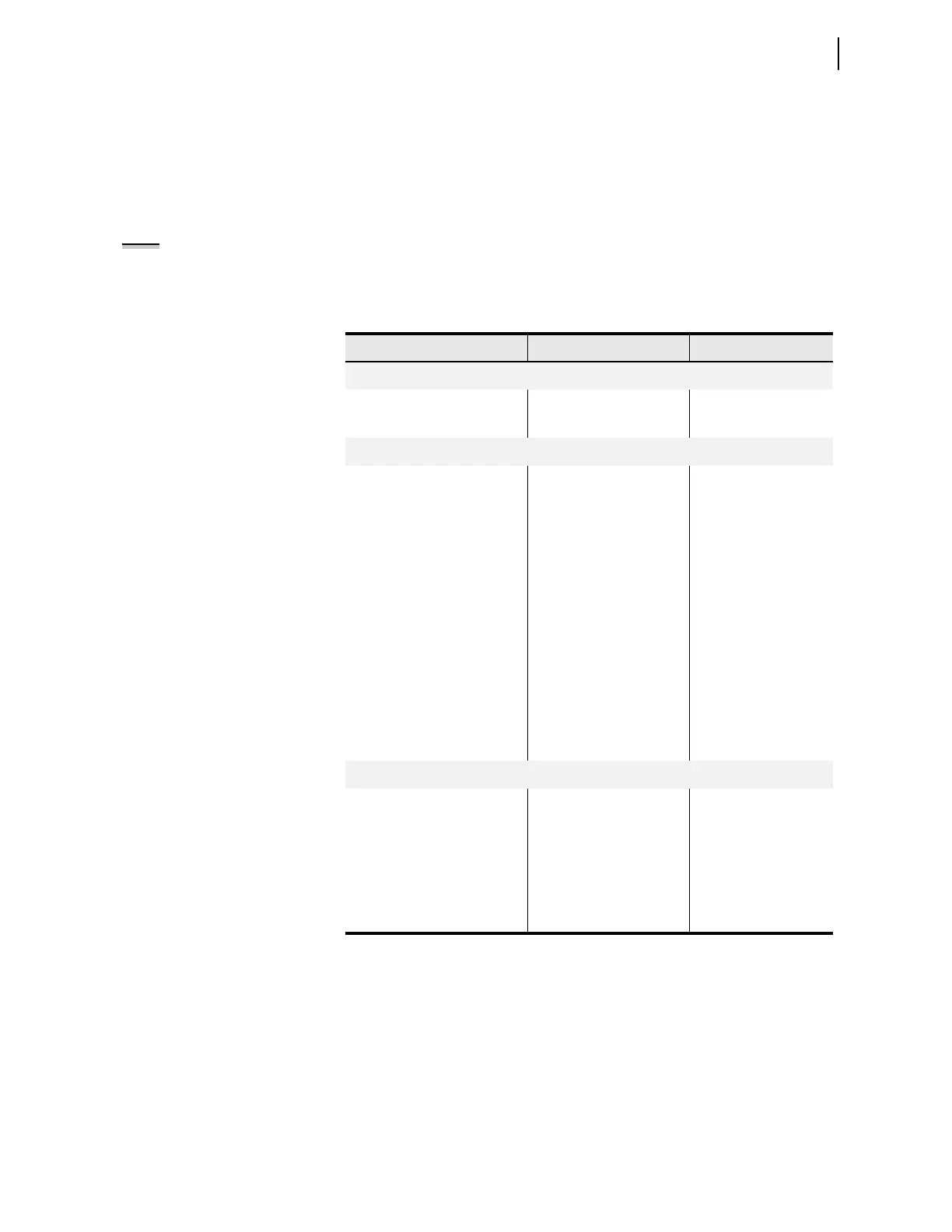
Setting Example Setting Comment
Group 1 > Set 1 > Trip and Close Logic
52A IN101
52B IN102
Group 1 > Logic 1 > SELOGIC Variables and Timers
SV01 (52A AND 52B) OR
(NOT 52A AND NOT 52B)
(XNOR gate)
SV01PU 0.5 Set pickup time to indi-
cate alarm for undeter-
mined breaker state
SV01DO 0.0
SV02 NOT SV01 AND 52A Indicates breaker close
status when asserted
SV02PU 0.0
SV02DO 0.0
SV03 NOT SV01 AND 52B Indicates breaker open
status when asserted
SV03PU 0.0
SV03DO 0.0
Touchscreen > Bay Control > Bay Screen 1
Breaker Mode CONTROL Controllable breaker
Breaker Close Status SV02T
Breaker Open Status SV03T
Breaker Alarm Status SV01T
Breaker HMI Close Command
a
a
Settings are forced to CC and OC, respectively, and are not available for setting.
CC
Breaker HMI Open Command
a
OC
NOTE: The relay does not support
dual-point breaker status (see Bay
Control Breaker Settings) and uses
the 52A Relay Word bit as the state
of the breaker in several of the
protection elements, including trip
and close logic. If you intend to
indicate dual-point status on the bay
control single-line diagram, make use
of SEL
OGIC to program this logic
similar to the one shown in Figure 9.1.