8-6 Phaser 7500 Printer Service Manual
Service Parts Disassembly
Overview
This section contains the removal procedures for field-replaceable parts of the
printer listed in the Parts List. In most cases, the replacement procedure is simply
the reverse of the removal procedure. In some instances, additional steps are
necessary and are provided for replacement of the parts. For specific assemblies
and parts, refer to the ““Parts List” on page 9-1”.
Always use the correct type and size screw (page 8-8). Using the wrong screw
can damage tapped holes. Do not use excessive force to remove or install
either a screw or a printer part.
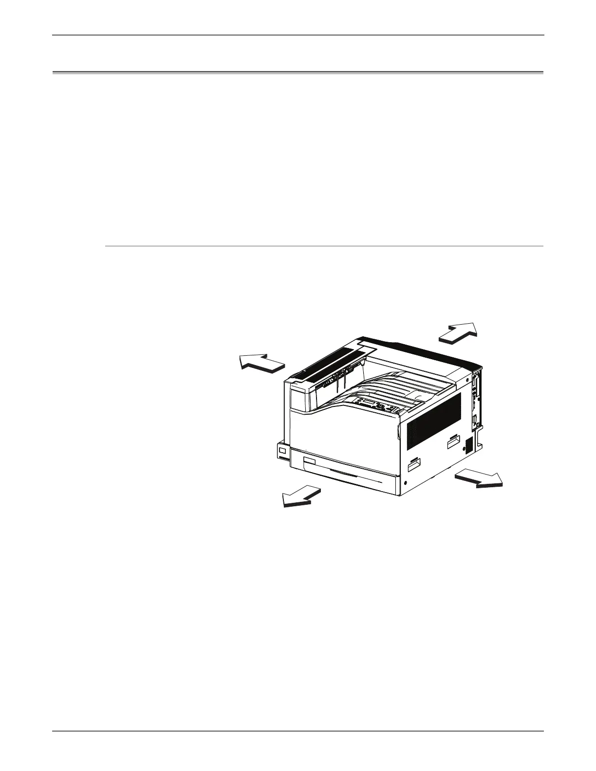
Standard Orientation of the Printer
When needed, the orientation of the printer is called out in the procedure as an aid
for locating the printer parts. The following figure identifies the Front, Rear, Left,
and Right sides of the printer.
s7500-070
Left
Right
Front
Rear
 Loading...


