8-22 Phaser 7500 Printer Service Manual
Service Parts Disassembly
REP 2.4 LPH Rear PWB
PL2.2.5
Do not expose the Imaging Unit to light for more than 5 minutes. Cover the
Imaging Unit to avoid damage. Do not touch the surface of the Imaging Unit.
1. Remove the Imaging Unit (C/M/Y/K) (REP 1.2, page 8-10).
2. Remove the Top Rear Cover and the Rear Cover (REP 19.6, page 8-217).
3. Remove the Right Cover (REP 19.8, page 8-219)
4. Remove the PWB Chassis Unit (REP 18.10, page 8-197).
5. Remove the HVPS (1st/2nd/DTS) (REP 6.4, page 8-65).
6. Remove the Drum/ Deve Drive Assembly (REP 3.8, page 8-33).
7. Remove 2 screws (silver, 8mm) that secure the Harness Guide and release the
Harness Guide by sliding it upwards.
8. Disconnect the wiring harness connector that is connected to the LPH Rear
PWB.
9. Slightly pull out the LPH Unit (refer to REP 2.1, page 8-18). Do not remove the
LPH.
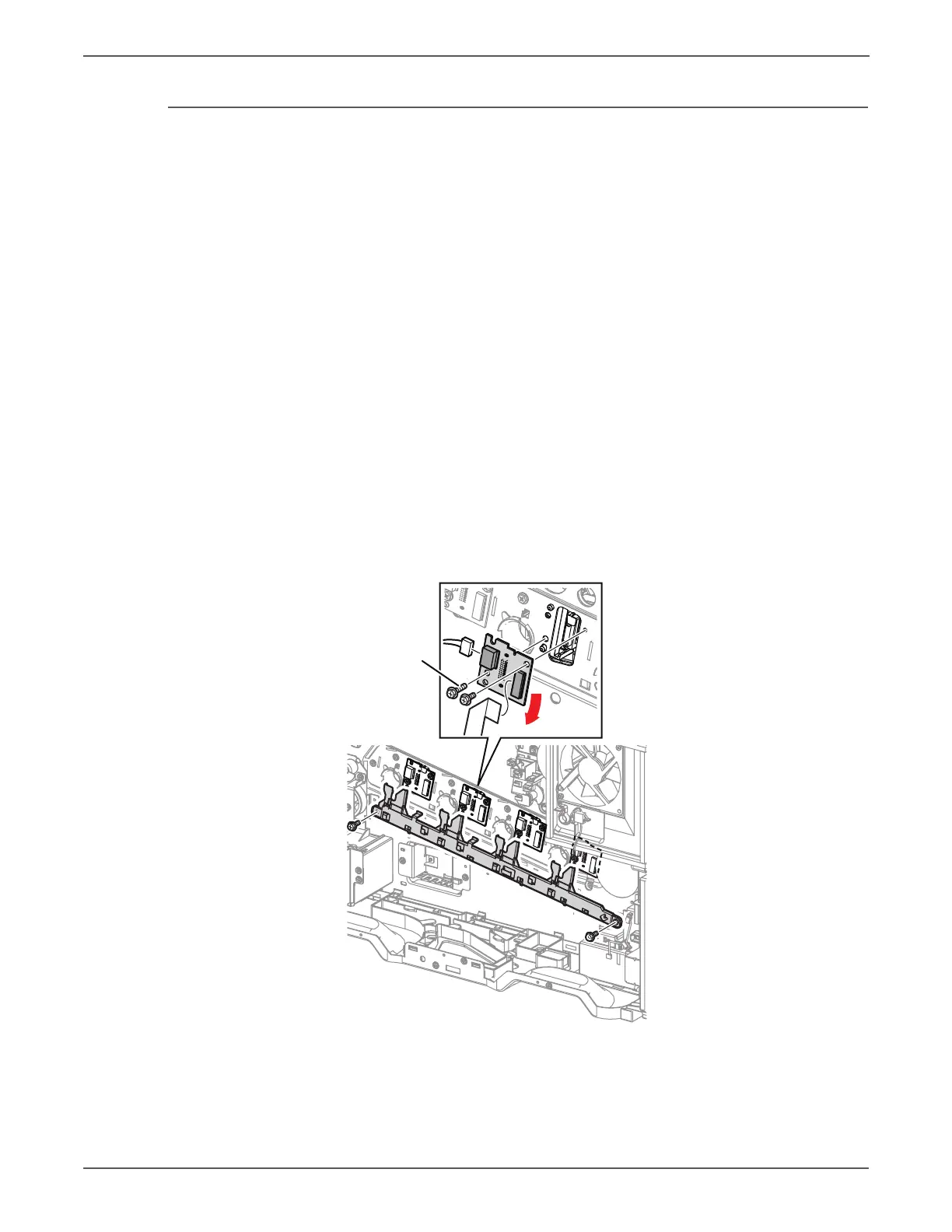
10. Lift the latch on the flat cable and release the cable.
11. Remove 2 screws (silver, 6mm/14mm) that secure the LPH Rear PWB and pull
down the LPH Rear PWB to remove it.
Be sure the Black plastic latch is always pulled forward in order to sit the PWB
in place. Be sure to push the LPH back in place.
 Loading...


