EasyManuals Logo

Xerox PHASER 7500 Service Manual

Xerox PHASER 7500
992 pages
To Next Page IconTo Next Page
To Previous Page IconTo Previous Page
Page #748 background imageLoading...
Page #748 background image
8-186 Phaser 7500 Printer Service Manual
Service Parts Disassembly
Electrical
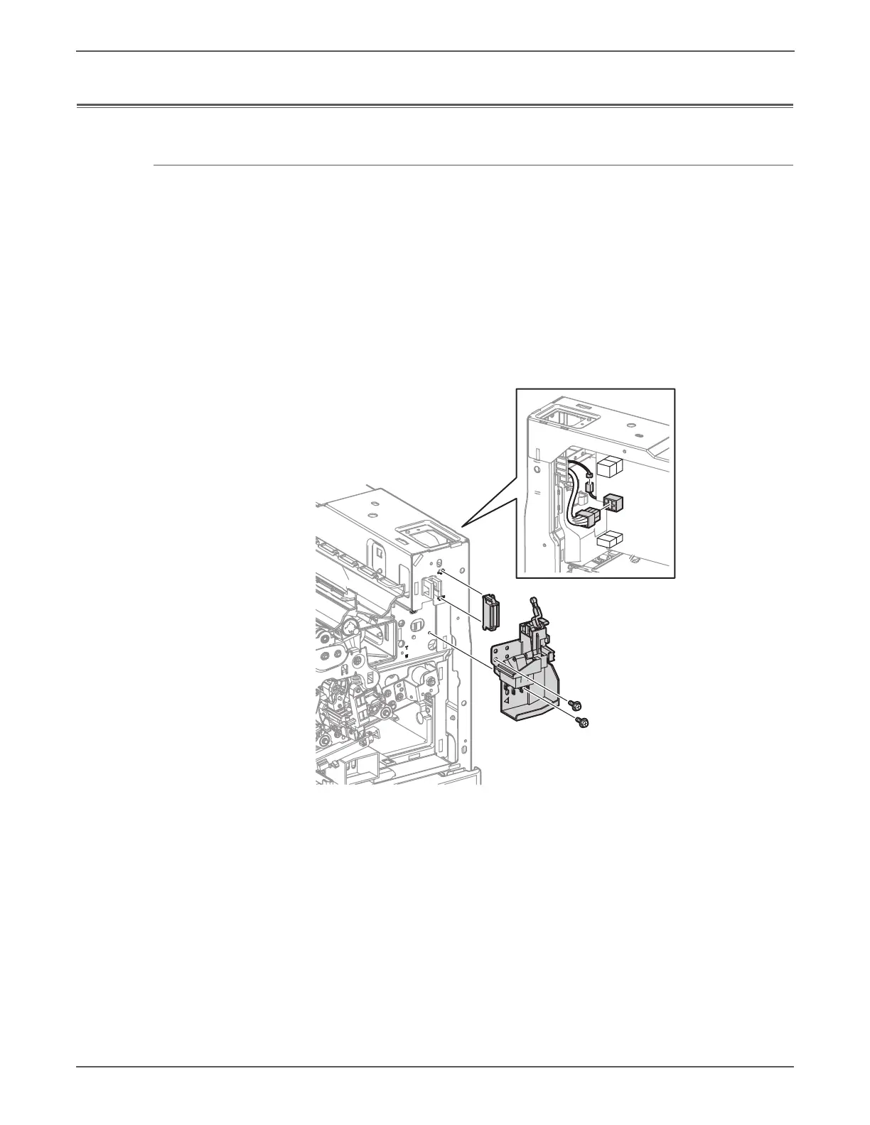
REP 18.1 Main Power Switch Chassis Assembly
PL18.1.1
1. Remove the Top Cover Assembly (REP 19.2, page 8-211).
2. Remove the Right Cover. (REP 19.8, page 8-219).
3. Disconnect the 2 wiring harness connectors that are connected to the Main
Power Switch Chassis Assembly.
4. Remove ATC Sensor PWB (REP 5.6, page 8-52).
5. Remove the Waste Toner Pipe Assembly (REP 8.6, page 8-75).
6. Remove 2 screws (silver, 6mm) that secure the Main Power Switch Chassis
Assembly and remove the Main Power Switch Chassis Assembly.
s7500-244

Table of Contents

Other manuals for Xerox PHASER 7500

Questions and Answers:

Question and Answer IconNeed help?

Do you have a question about the Xerox PHASER 7500 and is the answer not in the manual?

Xerox PHASER 7500 Specifications

General IconGeneral
Max Print Resolution1200 x 1200 dpi
Monthly Duty Cycle150, 000 pages
Standard Paper Capacity550 sheets
Duplex PrintingOptional
Standard Memory256 MB
Network Connectivity10/100/1000Base-T Ethernet
Supported Operating SystemsWindows, Mac OS, Linux
Max Paper Capacity2, 100 sheets
ConnectivityUSB 2.0, Ethernet
PDLPostScript 3, PCL 6, PDF
Print SpeedUp to 35 ppm

Related product manuals