EasyManuals Logo

Xerox PHASER 7500 Service Manual

Xerox PHASER 7500
992 pages
To Next Page IconTo Next Page
To Previous Page IconTo Previous Page
Page #662 background imageLoading...
Page #662 background image
8-100 Phaser 7500 Printer Service Manual
Service Parts Disassembly
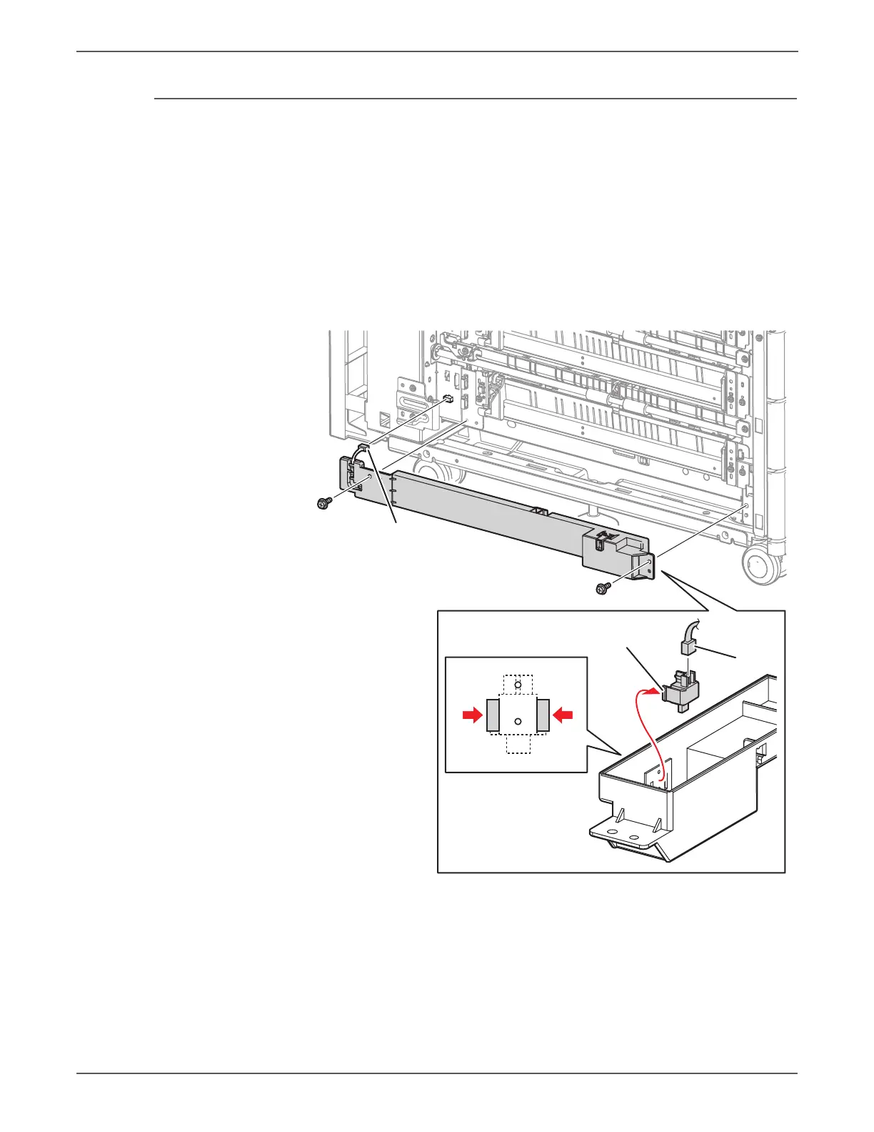
REP 10.12 Tray Module L/H Cover Switch
PL10.11.2
1. Remove the Left Cover (REP 10.21, page 8-109).
2. Disconnect the wiring harness connector P/J668 that connects the Cover to
the Tray Module (3T).
3. Remove 2 screws (silver, 8mm) that secure the Cover to the Tray Module (3T)
and remove the Cover.
4. Disconnect the wiring harness connector P/J104 that is connected to the Tray
Module L/H Cover Switch.
5. Release the 2 hooks that secure the Tray Module L/H Cover Switch to the Cover
and remove the Tray Module L/H Cover Switch.
s7500-164
Tray Module L/H Cover Switch
P/J668
P/J104

Table of Contents

Other manuals for Xerox PHASER 7500

Questions and Answers:

Question and Answer IconNeed help?

Do you have a question about the Xerox PHASER 7500 and is the answer not in the manual?

Xerox PHASER 7500 Specifications

General IconGeneral
Max Print Resolution1200 x 1200 dpi
Monthly Duty Cycle150, 000 pages
Standard Paper Capacity550 sheets
Duplex PrintingOptional
Standard Memory256 MB
Network Connectivity10/100/1000Base-T Ethernet
Supported Operating SystemsWindows, Mac OS, Linux
Max Paper Capacity2, 100 sheets
ConnectivityUSB 2.0, Ethernet
PDLPostScript 3, PCL 6, PDF
Print SpeedUp to 35 ppm

Related product manuals