EasyManuals Logo

Xerox PHASER 7500 Service Manual

Xerox PHASER 7500
992 pages
To Next Page IconTo Next Page
To Previous Page IconTo Previous Page
Page #932 background imageLoading...
Page #932 background image
10-32 Phaser 7500 Printer Service Manual
Plug/Jack and Wiring Diagrams
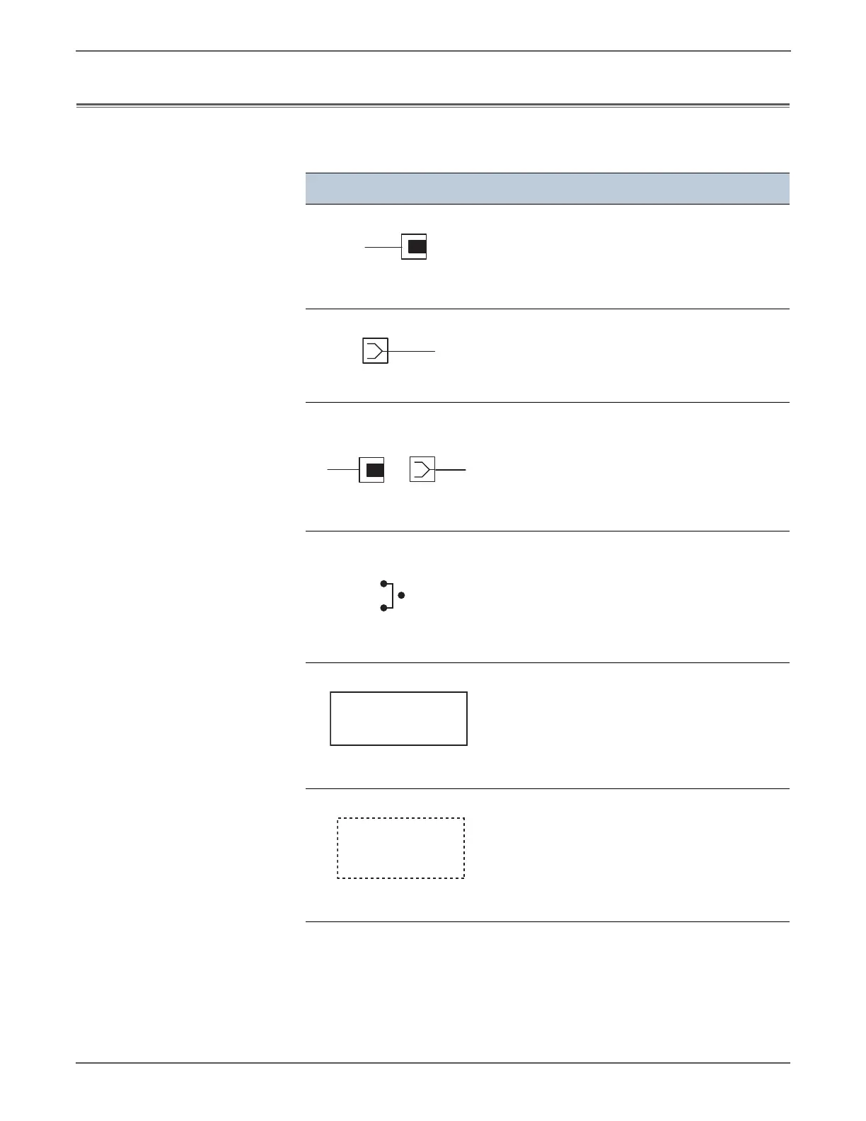
Notations Used in the Wiring Diagrams
The following table lists the symbols used in the wiring diagrams.
Symbol Description
Denotes a Plug.
Denotes a Jack.
Denotes Pin yy and Jack yy of the connector
Pxx and Jxx.
Denotes a Jumper Point (JPxxx/xxx). Each end
of the Jumper connection has a numeric
designation.
Denotes the parts.
PL X.Y.Z implies the item “Z” of plate (PL) “X.Y”
in Parts List.
Denotes functional parts attached with
functional parts name.
Plug
Jack
P/Jxx
YY
Plug and Jack
JPxxx
Jumper
Fuser
PL X.Y.Z
Subassembly 1
Heater
Subassembly 2

Table of Contents

Other manuals for Xerox PHASER 7500

Questions and Answers:

Question and Answer IconNeed help?

Do you have a question about the Xerox PHASER 7500 and is the answer not in the manual?

Xerox PHASER 7500 Specifications

General IconGeneral
Max Print Resolution1200 x 1200 dpi
Monthly Duty Cycle150, 000 pages
Standard Paper Capacity550 sheets
Duplex PrintingOptional
Standard Memory256 MB
Network Connectivity10/100/1000Base-T Ethernet
Supported Operating SystemsWindows, Mac OS, Linux
Max Paper Capacity2, 100 sheets
ConnectivityUSB 2.0, Ethernet
PDLPostScript 3, PCL 6, PDF
Print SpeedUp to 35 ppm

Related product manuals