8-200 Phaser 7500 Printer Service Manual
Service Parts Disassembly
REP 18.11 Backplane (BP) PWB (Interface PWB)
PL18.3.2
PWB’s can be damaged by an electrostatic discharge. Observe all ESD
procedures to avoid component damage.
1. Remove the Top Rear Cover and the Rear Cover (REP 19.6, page 8-217).
2. Remove the Image Processor Board (REP 21.1, page 8-220).
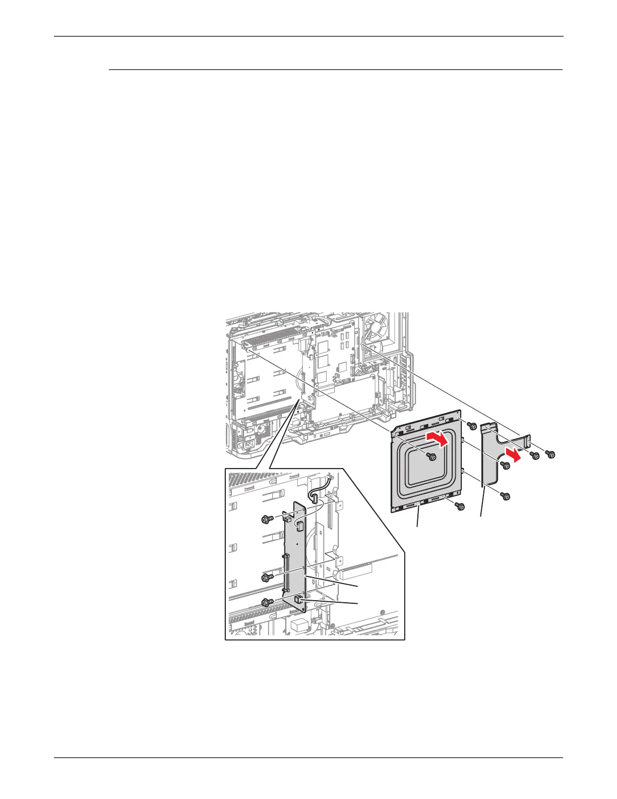
3. Remove 4 screws (silver, 6mm) that secure the MCU PWB Cover and remove
the MCU PWB Cover.
4. Remove 3 screws (silver, 6mm) that secure the ESS Cover and remove the ESS
Cover.
5. Disconnect the wiring harness connector that is connected to the Backplane
PWB.
6. Remove 3 screws (silver, 6mm) that secure the Backplane PWB, disconnect the
wiring harness connector that is connected to the MCU PWB, and remove the
Backplane PWB.
s7500-257
ESS Cover
MCU PWP Cover
BP PWB
EEPROM
 Loading...


