EasyManuals Logo

Xerox PHASER 7500 Service Manual

Xerox PHASER 7500
992 pages
To Next Page IconTo Next Page
To Previous Page IconTo Previous Page
Page #701 background imageLoading...
Page #701 background image
Phaser 7500 Printer Service Manual 8-139
Service Parts Disassembly
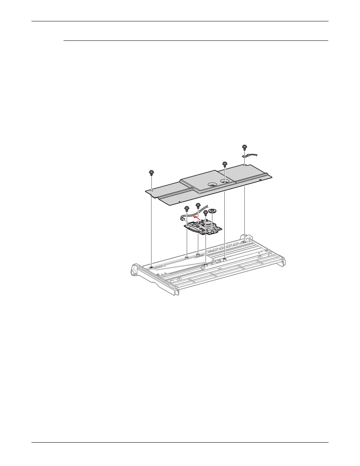
REP 13.10 Tray 1 Paper Size Sensor
PL13.5.4
1. Remove the Extension Tray (L1) together with the Extension Tray (L2) (REP
13.11, page 8-141).
2. Remove 3 screws (silver, Tapped, 5mm) that secure the Plate, together with
the Ground Wire.
3. Raise the right side of the Plate and remove it from the 3 hooks at the front.
4. Remove the Pinion Gear.
5. Remove 3 screws (silver, Plastic Tapped, 5mm) that secure the Tray 1 Paper
Size Sensor, and remove the Tray 1 Paper Size Sensor.
6. Release the wiring harness from the Harness Guide and disconnect the wiring
harness connector that is connected to the Tray 1 Paper Size Sensor.
s7500-200

Table of Contents

Other manuals for Xerox PHASER 7500

Questions and Answers:

Question and Answer IconNeed help?

Do you have a question about the Xerox PHASER 7500 and is the answer not in the manual?

Xerox PHASER 7500 Specifications

General IconGeneral
Max Print Resolution1200 x 1200 dpi
Monthly Duty Cycle150, 000 pages
Standard Paper Capacity550 sheets
Duplex PrintingOptional
Standard Memory256 MB
Network Connectivity10/100/1000Base-T Ethernet
Supported Operating SystemsWindows, Mac OS, Linux
Max Paper Capacity2, 100 sheets
ConnectivityUSB 2.0, Ethernet
PDLPostScript 3, PCL 6, PDF
Print SpeedUp to 35 ppm

Related product manuals