EasyManuals Logo

Xerox PHASER 7500 Service Manual

Xerox PHASER 7500
992 pages
To Next Page IconTo Next Page
To Previous Page IconTo Previous Page
Page #580 background imageLoading...
Page #580 background image
8-18 Phaser 7500 Printer Service Manual
Service Parts Disassembly
LED Print Head
REP 2.1 LED Print Head (LPH) Unit (Y/M/C/K)
PL2.1.2
1. Remove the Waste Cartridge (REP 1.3, page 8-12).
2. Remove the Front Cover Assembly and the Inner Cover Assembly (REP 19.1,
page 8-207).
3. Remove the ATC Sensor Board (REP 5.6, page 8-52).
4. Remove the Waste Toner Pipe Assembly (REP 8.6, page 8-75).
5. Remove the Deve Plate Assembly (REP 5.4, page 8-49).
6. Remove the Developer Housing Assembly (K) (REP 5.5, page 8-50).
Note
Do not apply force to the LPH positioning pin.
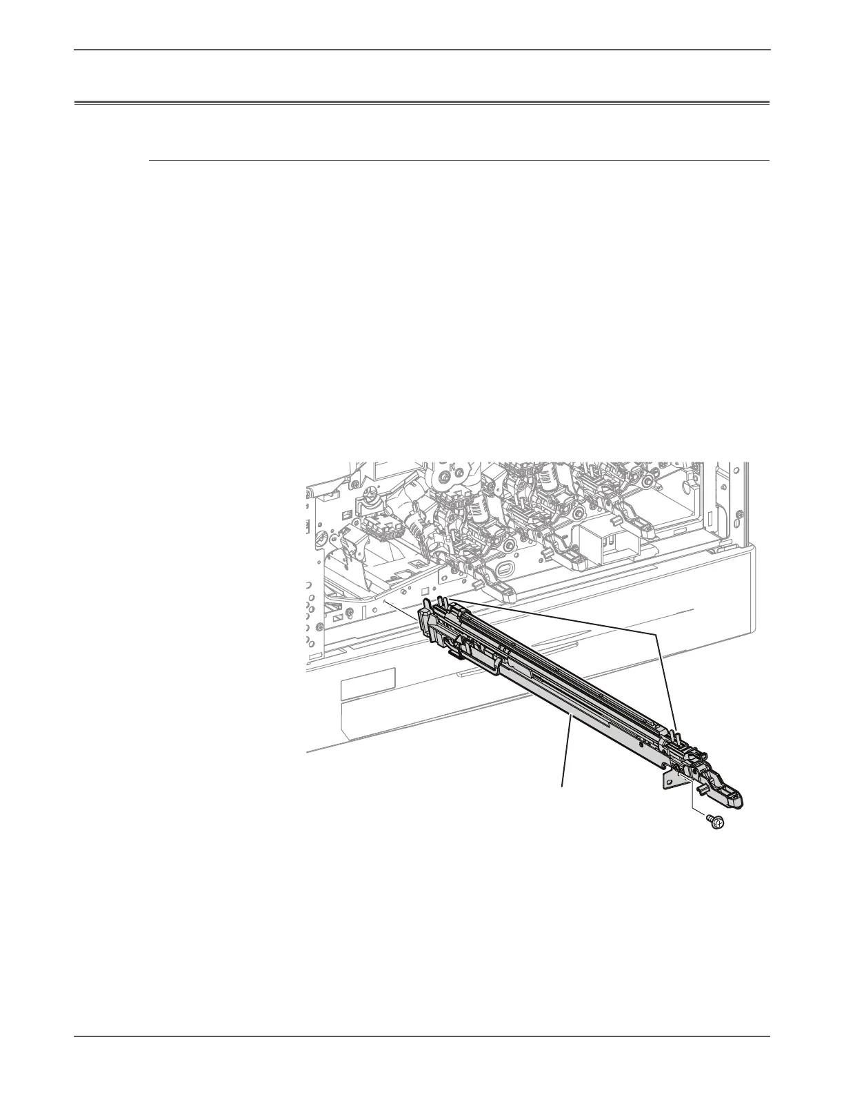
7. Remove the screw (silver, 6mm) that secures the LPH Unit (K).
8. Pull and raise the LPH Unit (K) to remove it.
s7500-073
LED Print Head Unit (K)
Positioning Pins

Table of Contents

Other manuals for Xerox PHASER 7500

Questions and Answers:

Question and Answer IconNeed help?

Do you have a question about the Xerox PHASER 7500 and is the answer not in the manual?

Xerox PHASER 7500 Specifications

General IconGeneral
Max Print Resolution1200 x 1200 dpi
Monthly Duty Cycle150, 000 pages
Standard Paper Capacity550 sheets
Duplex PrintingOptional
Standard Memory256 MB
Network Connectivity10/100/1000Base-T Ethernet
Supported Operating SystemsWindows, Mac OS, Linux
Max Paper Capacity2, 100 sheets
ConnectivityUSB 2.0, Ethernet
PDLPostScript 3, PCL 6, PDF
Print SpeedUp to 35 ppm

Related product manuals