Phaser 7500 Printer Service Manual 8-203
Service Parts Disassembly
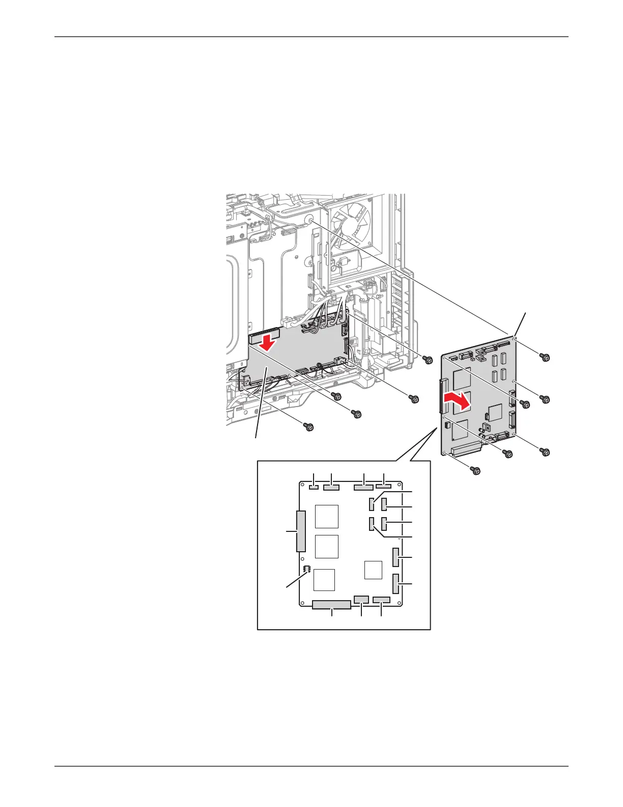
3. Remove 5 screws (silver, 6mm) that secure the Motor Drive PWB to the PWB
Chassis Unit.
4. Lower the Motor Drive PWB and disconnect the wiring harness connector that
is connected to the MCU PWB.
5. Disconnect all connectors that are connected to the MCU PWB.
6. Remove 6 screws (silver, 6mm) that secure the MCU PWB to the PWB Chassis
Unit.
7. Shift the MCU PWB to the left, disconnect the wiring harness connector that is
connected to the BP PWB, and remove the MCU PWB.
8. Remove the EEPROM for transferring to the new PWB.
Be sure to update firmware after installing the MCU PWB.
s7500-259
MD PWB
MCU PWB
416
411 415
431
554
555
557
556
417
414
412401452
451
EEPROM
 Loading...


