8-212 Phaser 7500 Printer Service Manual
Service Parts Disassembly
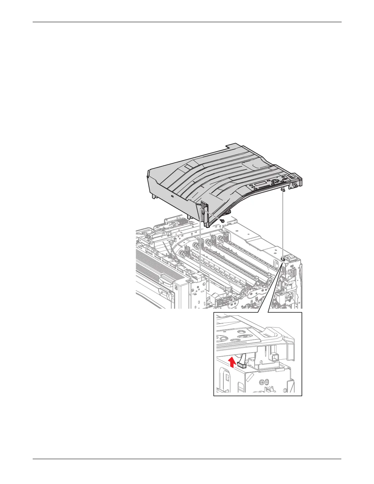
10. Remove 1 screw (silver, 8mm) that secures the Top Cover Assembly to the
printer.
Do not lift the Top Cover too abruptly, because the wiring harness of the
Control Panel is still connected, when removing the Control Panel in the
following steps.
Check the connector beside the Main Switch by slightly lifting up the right side
of the Top Cover Assembly.
11. Lift up the right side of the Top Cover Assembly to disconnect the Control
Panel connector, release the 2 hooks in the rear and 1 hook on the left side,
and remove the Top Cover Assembly.
 Loading...


