Phaser 7500 Printer Service Manual 8-213
Service Parts Disassembly
In the following step, check the connector beside the Main Switch by slightly
lifting up the right side of the Top Cover Assembly.
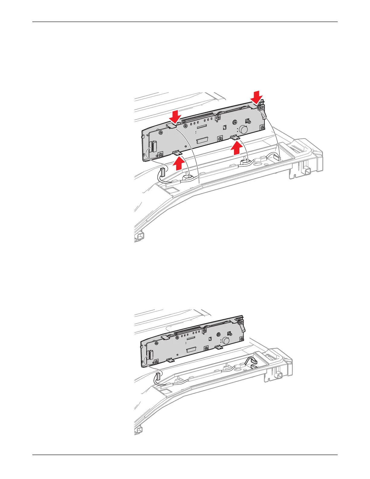
12. Release the 4 hooks that secure the Control Panel.
13. Disconnect the wiring harness connector that is connected to the bottom of
the Control Panel and remove the Control Panel.
Be careful not to pinch the Paper Weight when installing the Top Cover
Assembly.
Be sure to connect the 2 wiring harness connectors securely prior to installing
the Control Panel.
 Loading...


