EasyManuals Logo

Xerox PHASER 7500 Service Manual

Xerox PHASER 7500
992 pages
To Next Page IconTo Next Page
To Previous Page IconTo Previous Page
Page #934 background imageLoading...
Page #934 background image
10-34 Phaser 7500 Printer Service Manual
Plug/Jack and Wiring Diagrams
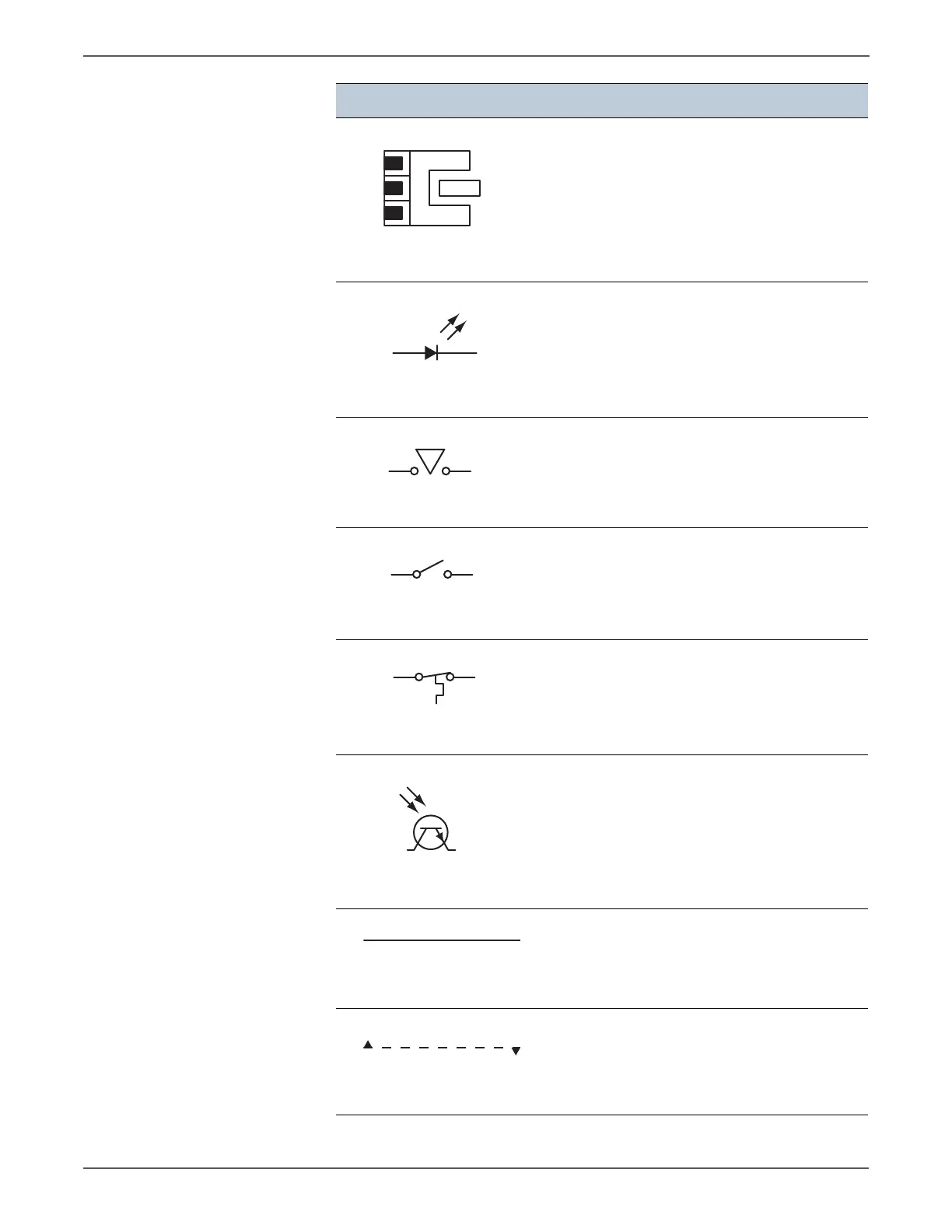
Denotes a Photo Sensor.
Denotes an LED.
Denotes a Safety Interlock Switch.
Denotes an On-Off Switch (single-pole, single-
throw switch).
Denotes an On-Off Switch (Temperature -
normally close).
Denotes an NPN Photo-transistor.
Represents an interconnection between parts
using wiring harness or wire.
Represents an interconnection which differs
according to the specifications.
Symbol Description
Optic Sensor
LED
Safety Interlock Switch
On Off Switch
Temperature Switch
NPN Phototransistor
Interconnection
Interconnection, Differing

Table of Contents

Other manuals for Xerox PHASER 7500

Questions and Answers:

Question and Answer IconNeed help?

Do you have a question about the Xerox PHASER 7500 and is the answer not in the manual?

Xerox PHASER 7500 Specifications

General IconGeneral
Max Print Resolution1200 x 1200 dpi
Monthly Duty Cycle150, 000 pages
Standard Paper Capacity550 sheets
Duplex PrintingOptional
Standard Memory256 MB
Network Connectivity10/100/1000Base-T Ethernet
Supported Operating SystemsWindows, Mac OS, Linux
Max Paper Capacity2, 100 sheets
ConnectivityUSB 2.0, Ethernet
PDLPostScript 3, PCL 6, PDF
Print SpeedUp to 35 ppm

Related product manuals