Trace Port Interface Unit
17-22 Copyright © 2005-2008 ARM Limited. All rights reserved. ARM DDI 0337G
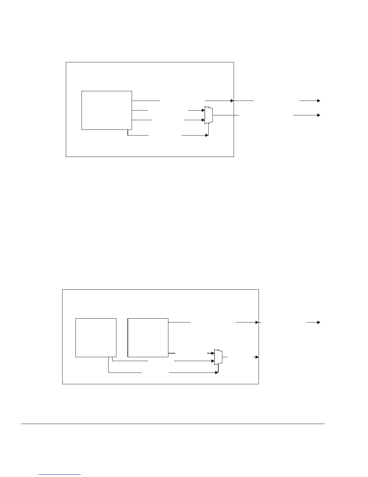
Figure 17-15 SWO shared with TRACEPORT
17.3.3 SWO Shared with JTAG-TDO
For minimal pin count, it is possible to overlay JTAG debug and SWO on the same
package pin. This approach is only recommended where there is no provision for a
conventional trace port, or for use with more complex system-level debug configuration
controls.
If this option is chosen, the Instrumentation Trace is not accessible while the debug port
is being used in a JTAG configuration. Serial wire debug and SWO can be used together
at the same time.
To implement this option, the JTAGNSW output from SWJ-DP is used to control the
multiplexor. Figure 17-16 shows the SWO shared with JTAG-TDO option.
Figure 17-16 SWO shared with JTAG-TDO
CM3TPIU
CortexM3Integration
TRACESWO
TRACEDATA[0]
TRACEDATA[3:1]
0
1
TRACEDATA[3:1]
SWV/TRACEDATA[0]
SWOACTIVE
SWJ-DP
CortexM3Integration
CM3TPIU
TRACEDATA[3:0]
TRACESWO
0
1
TDO/SWV
JTAGNSW
JTAGTDO
TRACEDATA[3:0]