Trace Port Interface Unit
17-10 Copyright © 2005-2008 ARM Limited. All rights reserved. ARM DDI 0337G
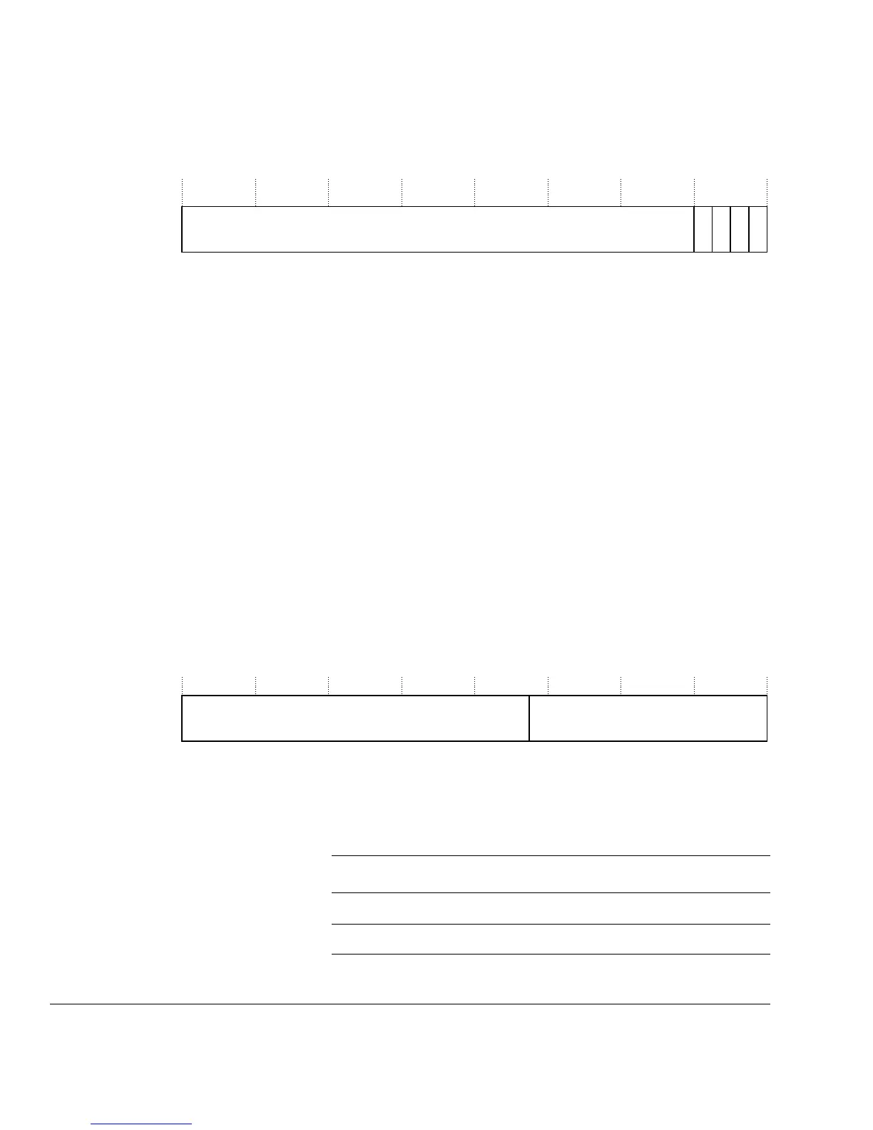
Figure 17-3 shows the bit assignments.
Figure 17-3 Supported Sync Port Size Register bit assignments
Current Sync Port Size Register
This register is read/write. The Current Sync Port Size Register has the same format as
the Supported Sync Port Sizes Register but only one bit is set, and all others must be
zero. Writing values with more than one bit set, or setting a bit that is not indicated as
supported is not supported and causes Unpredictable behavior.
It is more convenient to use the same format as the Supported Sync Port Sizes Register
because it saves on having to decode the sizes later on in the device, and also maintains
the format from the other register bank for checking for valid assignments.
On reset this defaults to the smallest possible port size, 1 bit, and so reads as
0x00000001
.
Async Clock Prescaler Register
Use the Async Clock Prescaler Register to scale the baud rate of the asynchronous
output.
Figure 17-4 shows the bit assignments of the Async Clock Prescaler Register.
Figure 17-4 Async Clock Prescaler Register bit assignments
Table 17-6 describes the bit assignments of the Async Clock Prescaler Register.
02 01
31 3210
04 03
Reserved
31 13 0
Reserved
12
PRESCALER
Table 17-6 Async Clock Prescaler Register bit assignments
Bits Field Function
[31:13] - Reserved. RAZ/SBZP.
[12:0] PRESCALER Divisor for TRACECLKIN is Prescaler + 1.