System Debug
ARM DDI 0337G Copyright © 2005-2008 ARM Limited. All rights reserved. 11-23
Unrestricted Access Non-Confidential
Table 11-12 describes the bit assignments of the DWT LSU Count Register.
DWT Fold Count Register
Use the DWT Fold Count Register to count the total number of folded instructions. This
counts 1 for each instruction that takes 0 cycles.
The register address, access type, and Reset state are:
Address
0xE0001018
Access Read/write
Reset state -
Figure 11-10 describes the bit assignments of the DWT Fold Count Register.
Figure 11-10 DWT Fold Count Register bit assignments
Table 11-13 describes the bit assignments of the DWT Fold Count Register.
Table 11-12 DWT LSU Count Register bit assignments
Bits Field Function
[31:8] - Reserved.
[7:0] LSUCNT LSU counter. This counts the total number of cycles that the processor is processing an LSU
operation. The initial execution cost of the instruction is not counted.
For example, an LDR that takes two cycles to complete increments this counter one cycle.
Equivalently, an LDR that stalls for two cycles (and so takes four cycles), increments this counter
three times. An event is emitted on counter overflow (every 256 cycles).
Clears to 0 on enabling.
Reserved
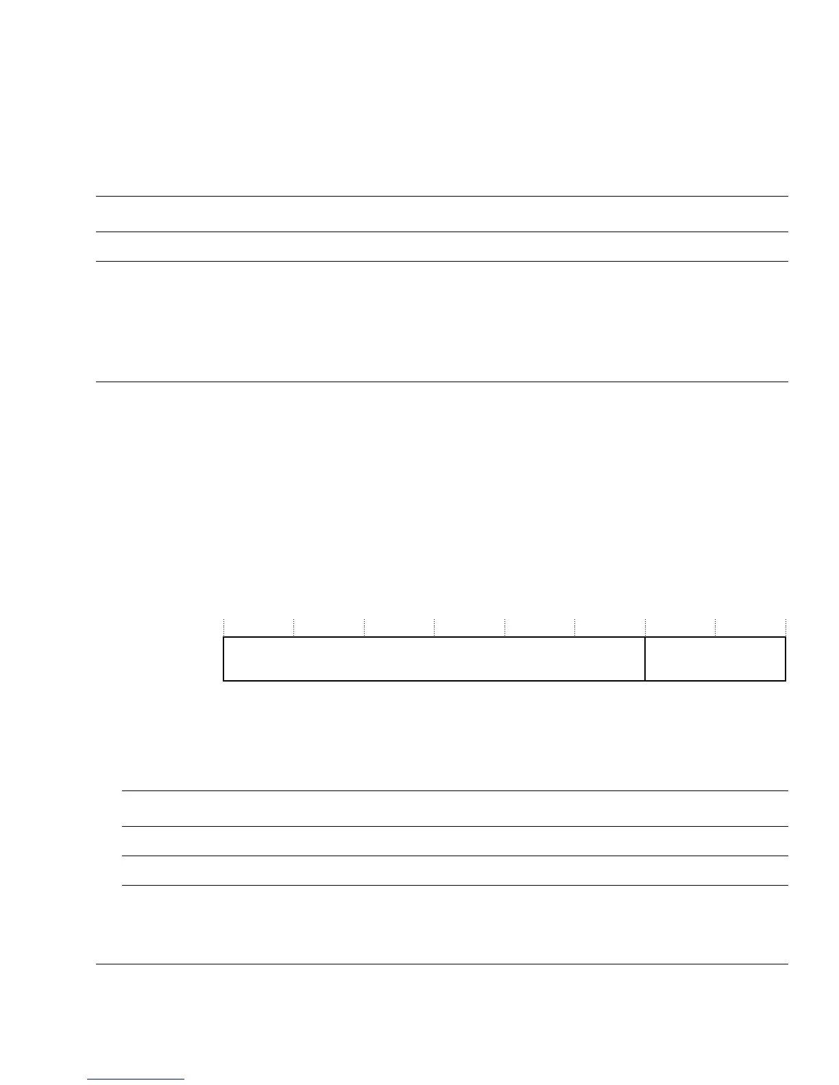
31 8 7 0
FOLDCNT
Table 11-13 DWT Fold Count Register bit assignments
Bits Field Function
[31:8] - Reserved.
[7:0] FOLDCNT This counts the total number folded instructions. This counter initializes to 0 when enabled.