EasyManuals Logo

ARM Cortex-M3 User Manual

ARM Cortex-M3
410 pages
To Next Page IconTo Next Page
To Previous Page IconTo Previous Page
Page #262 background imageLoading...
Page #262 background image
System Debug
11-34 Copyright © 2005-2008 ARM Limited. All rights reserved. ARM DDI 0337G
Non-Confidential
Unrestricted Access
ITM Trace Control Register
Use this register to configure and control ITM transfers.
Note
You can only write to this register in privilege mode.
The register address, access type, and Reset state are:
Access Read/write
Address
0xE0000E80
Reset
0x00000000
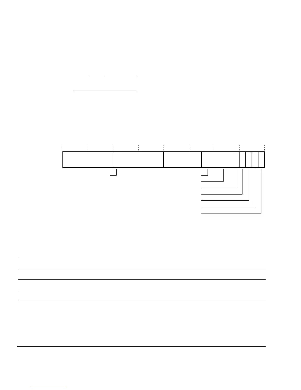
Figure 11-14 shows the ITM Control Register bit assignments.
Figure 11-14 ITM Trace Control Register bit assignments
Table 11-22 describes the bit assignments of the ITM Control Register.
31
43 0
12
7
9810
15
16
Reserved
SYNCENA
TSENA
ITMENA
TSPrescale
DWTENA
24
23
Reserved
ATBID
5
SWOENA
BUSY
22
Reserved
Table 11-22 ITM Trace Control Register bit assignments
Bits Field Function
[31:24] - 0b00000000.
[23] BUSY Set when ITM events present and being drained
[22:16] ATBID ATB ID for CoreSight system.
[15:10] - 0b000000.

Table of Contents

Questions and Answers:

Question and Answer IconNeed help?

Do you have a question about the ARM Cortex-M3 and is the answer not in the manual?

ARM Cortex-M3 Specifications

General IconGeneral
ArchitectureARMv7-M
Instruction SetThumb-2
Pipeline Stages3-stage
InterruptsNested Vectored Interrupt Controller (NVIC)
Interrupt ControllerNested Vectored Interrupt Controller (NVIC)
Memory Protection UnitOptional
Power ConsumptionVaries by implementation
Max Clock SpeedUp to 100 MHz
DebuggingJTAG and Serial Wire Debug (SWD)
Operating Voltage1.8V to 3.6V
Manufacturing ProcessVaries by implementation
Core Type32-bit

Related product manuals