Trace Port Interface Unit
17-4 Copyright © 2005-2008 ARM Limited. All rights reserved. ARM DDI 0337G
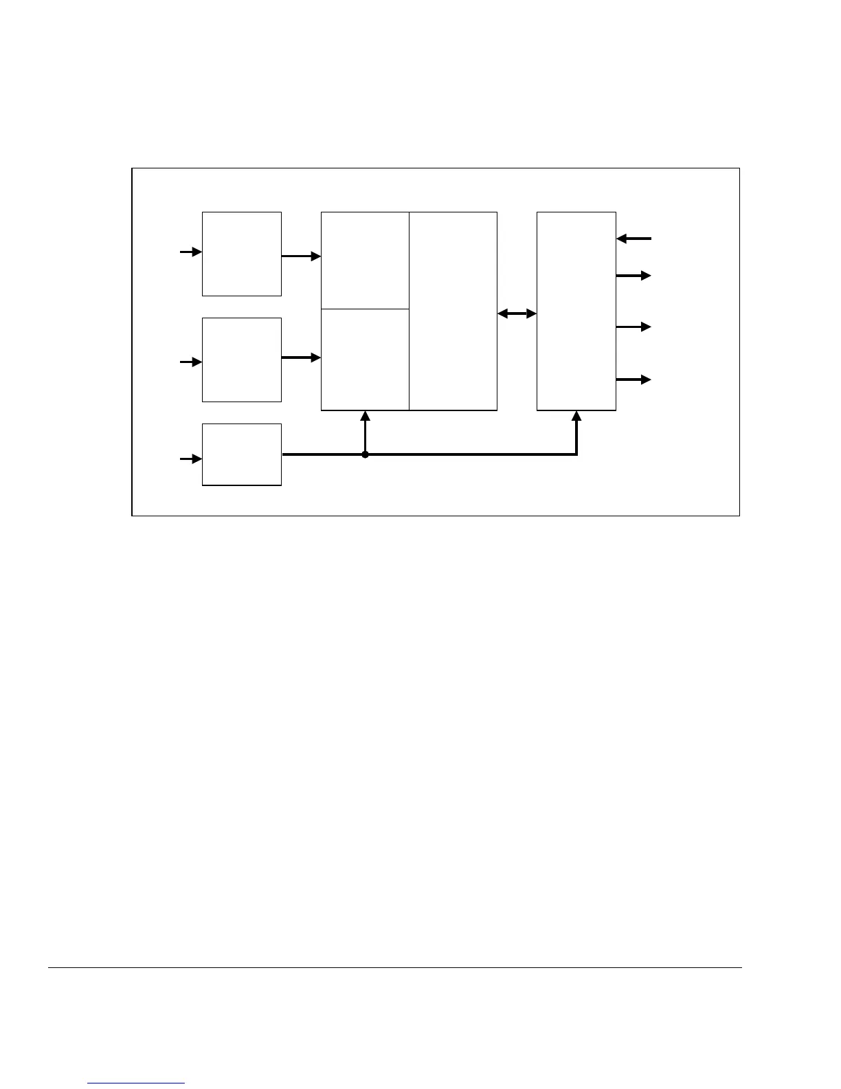
Figure 17-2 TPIU block diagram (ETM version)
17.1.2 TPIU components
A description of the main components of the TPIU is given in the following sections:
• Asynchronous FIFO
• Formatter
• Trace out on page 17-5
• Advanced Trace Bus interface on page 17-5
• Advanced Peripheral Bus interface on page 17-5.
Asynchronous FIFO
The asynchronous FIFO enables trace data to be driven out at a speed that is not
dependent on the speed of the core clock.
Formatter
The formatter inserts source ID signals into the data packet stream so that trace data can
be re-associated with its trace source. The formatter is always active when the
TRACEPORT mode is active.
ATB
Interface
APB
Interface
Trace Out
(serializer)
ETM
ATB
Slave
Port
APB
Slave
Port
TRACECLKIN
TRACECLK
TRACEDATA
[3:0]
TRACESWO
ATCLK Domain
TRACECLKIN Domain
ATB
Interface
ITM
ATB
Slave
Port
Formatter
Asynchronous
FIFO
Asynchronous
FIFO