Trace Port Interface Unit
17-18 Copyright © 2005-2008 ARM Limited. All rights reserved. ARM DDI 0337G
Reset state
0x0
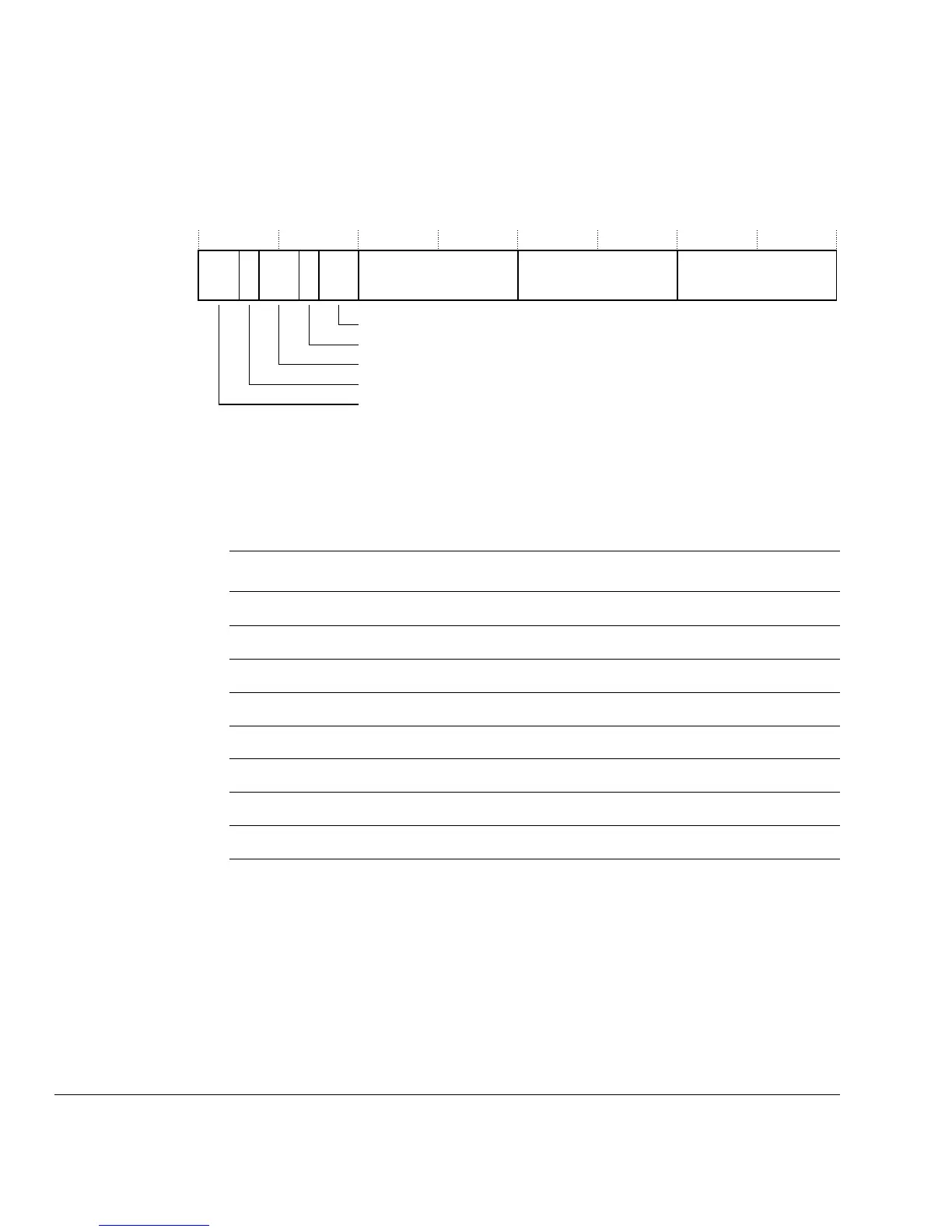
Figure 17-12 shows the bit assignments of the Integration register : FIFO data 0.
Figure 17-12 Integration register : FIFO data 0 bit assignments
Table 17-14 lists the bit assignments of the Integration register : FIFO data 0.
Integration Register : FIFO data 1
The register address, access type, and Reset state are:
Address
0xE0040EFC
Access Read only
Reset state
0x0
Figure 17-13 on page 17-19 shows the bit assignments of the Integration register : FIFO
data 1.
FIFO1 data 2 FIFO1 data 1
FIFO1 data 0
31 0
29 2728 26
2425
23
16
15
87
Write point 1
ATVALID1S
Write point 2
ATVALID2S
30
Reserved
Table 17-14 Integration register : FIFO data 0 bit assignments
Bits Field Function
[31:30] - Reserved
[29] ATVALID2S
[28:27] Write point 2
[26] ATVALID1S
[25:24] Write point 1
[23:16] FIFO1 data 2
[15:8] FIFO1 data 1
[7:0] FIFO1 data 0