Programmer’s Model
2-4 Copyright © 2005-2008 ARM Limited. All rights reserved. ARM DDI 0337G
Non-Confidential
Unrestricted Access
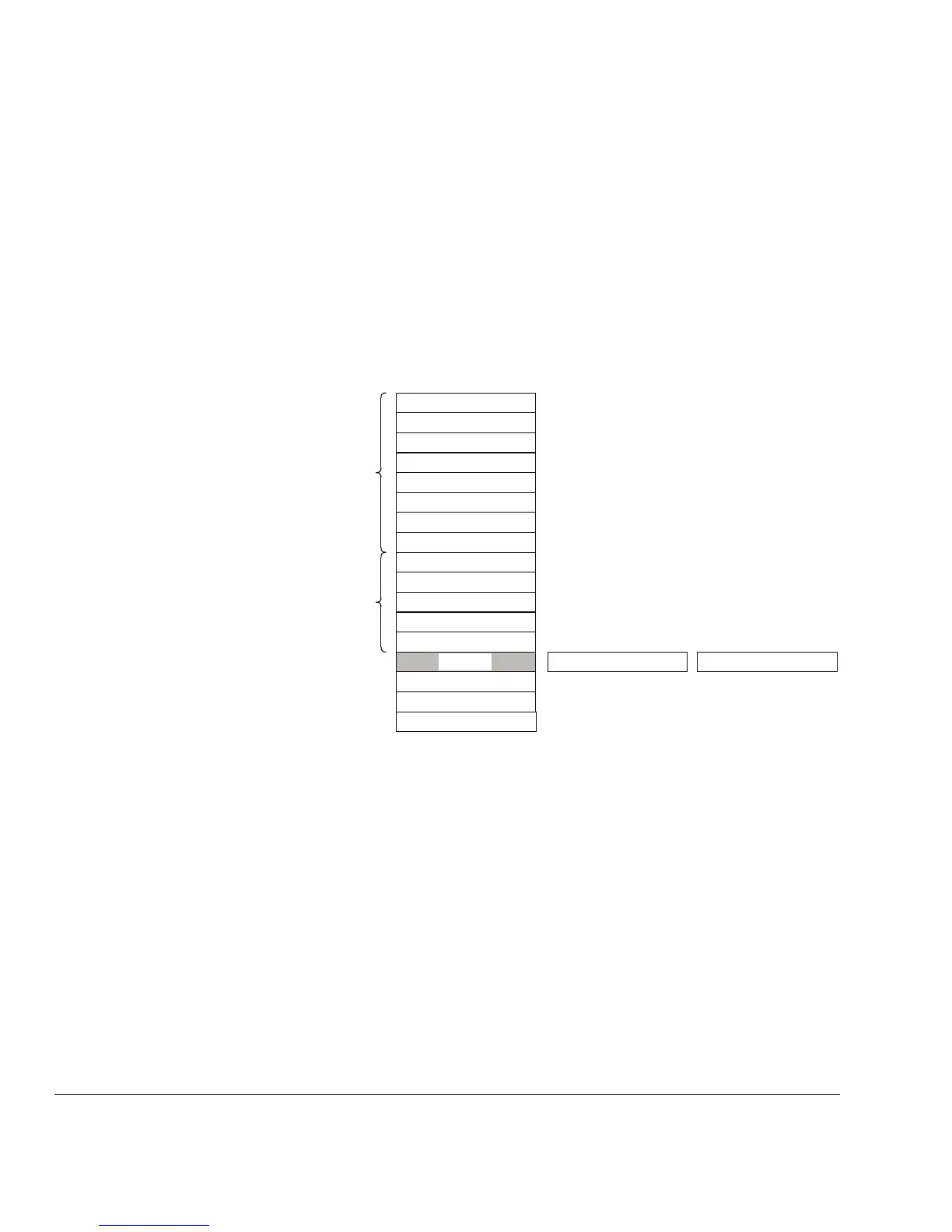
2.3 Registers
The processor has the following 32-bit registers:
• 13 general-purpose registers, r0-r12
• stack point alias of banked registers, SP_process and SP_main
• link register, r14
• program counter, r15
• one program status register, xPSR.
Figure 2-1 shows the processor register set.
Figure 2-1 Processor register set
2.3.1 General-purpose registers
The general-purpose registers r0-r12 have no special architecturally-defined uses. Most
instructions that can specify a general-purpose register can specify r0-r12.
Low registers Registers r0-r7 are accessible by all instructions that specify a
general-purpose register.
High registers Registers r8-r12 are accessible by all 32-bit instructions that
specify a general-purpose register.
Registers r8-r12 are not accessible by all 16-bit instructions.
Program Status Register
r13 (SP)
r14 (LR)
r15 (PC)
r5
r6
r7
r0
r1
r3
r4
r2
r10
r11
r12
r8
r9
low registers
high registers
SP_mainSP_process
xPSR