System Debug
11-20 Copyright © 2005-2008 ARM Limited. All rights reserved. ARM DDI 0337G
Non-Confidential
Unrestricted Access
• Applications and debuggers can use the counter to measure elapsed execution
time. By subtracting a start and an end time, an application can measure time
between in-core clocks (other than when Halted in debug). This is valid to 2
32
core clock cycles (for example, almost 86 seconds at 50MHz).
DWT CPI Count Register
Use the DWT CPI Count Register to count the total number of instruction cycles beyond
the first cycle.
The register address, access type, and Reset state are:
Address
0xE0001008
Access Read-write
Reset state -
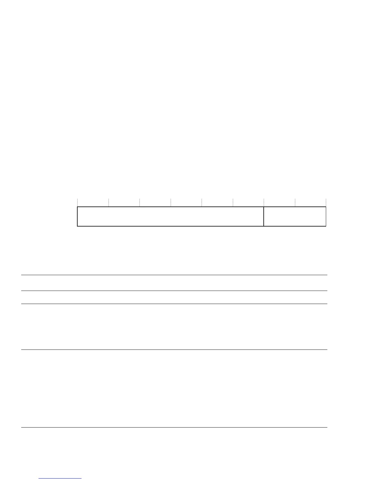
Figure 11-6 shows the bit assignments of the DWT CPI Count Register.
Figure 11-6 DWT CPI Count Register bit assignments
Table 11-9 describes the bit assignments of the DWT CPI Count Register.
DWT Exception Overhead Count Register
Use the DWT Exception Overhead Count Register to count the total cycles spent in
interrupt processing.
The register address, access type, and Reset state are:
Address
0xE000100C
Reserved
31 8 7 0
CPICNT
Table 11-9 DWT CPI Count Register bit assignments
Bits Field Function
[31:8] - Reserved.
[7:0] CPICNT Current CPI counter value. Increments on the additional cycles (the first cycle is not counted)
required to execute all instructions except those recorded by DWT_LSUCNT. This counter also
increments on all instruction fetch stalls.
If CPIEVTENA is set, an event is emitted when the counter overflows.
Clears to 0 on enabling.