Introduction
ARM DDI 0337G Copyright © 2005-2008 ARM Limited. All rights reserved. 1-5
Unrestricted Access Non-Confidential
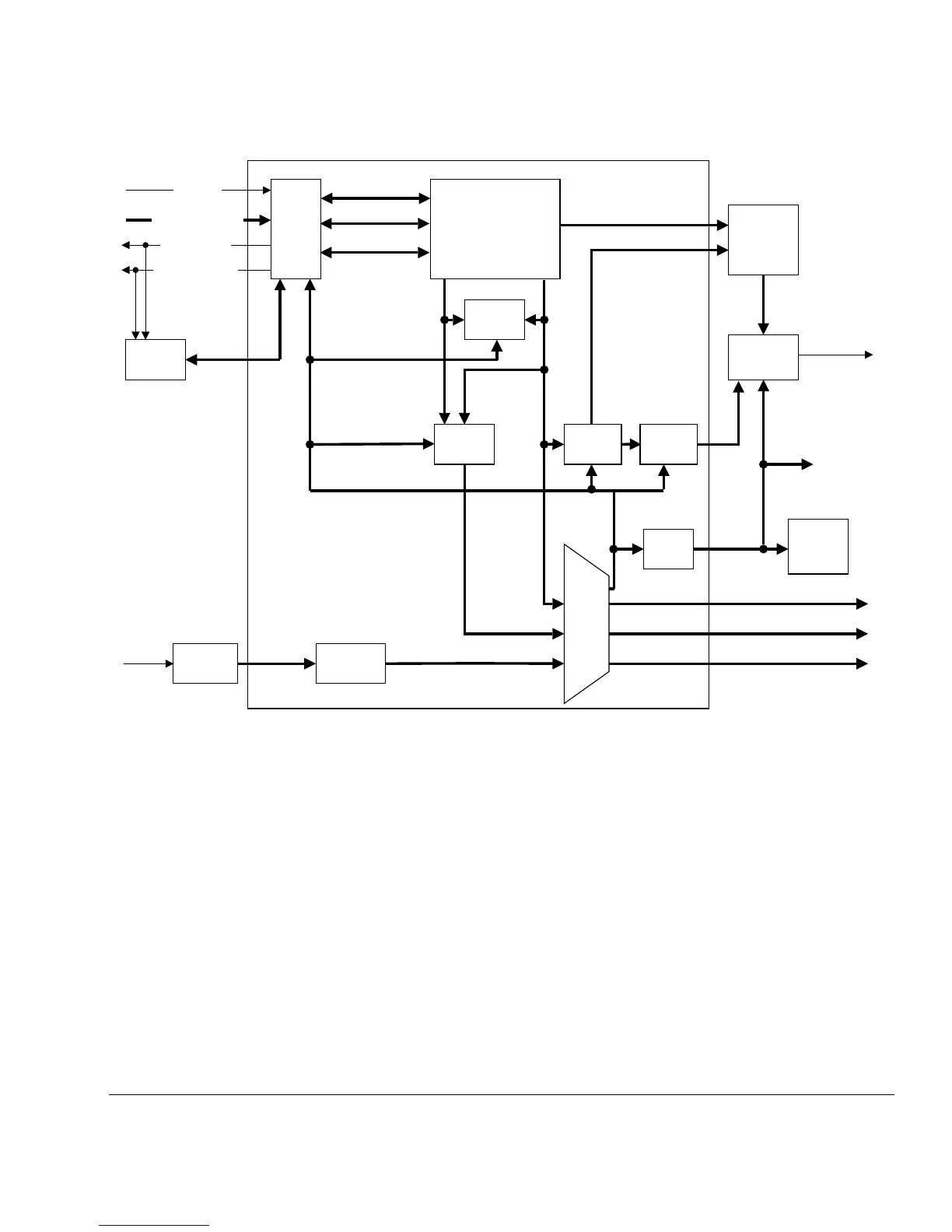
Figure 1-1 Cortex-M3 block diagram
1.2.1 Processor core
The processor core implements the ARMv7-M architecture. It has the following main
features:
• Thumb instruction set subset, consisting of all base Thumb instructions, 16-bit
and 32-bit. See the ARMv7-M Architecture Reference Manual for more
information.
• Harvard processor architecture enabling simultaneous instruction fetch with data
load/store.
• Three-stage pipeline.
• Single cycle 32-bit multiply.
Optional
ETM
Private Peripheral Bus
(internal)
Optional
DWT
Trigger
Optional
ITM
Optional
TPIU
CM3Core
Instr. Data
Optional
FPB
Optional
MPU
Optional
AHB-AP
NVIC
SW/
SWJ-DP
Bus
Matrix
APB
i/f
I-code bus
D-code bus
System bus
Optional
ROM
Table
Private
Peripheral
Bus
(external)
Trace port
(serial wire
or multi-pin)
Cortex-M3
SW/
JTAG
Debug
Sleep
Interrupts
INTNMI
SLEEPING
SLEEPDEEP
INTISR[239:0]
Optional
WIC