Nested Vectored Interrupt Controller
8-30 Copyright © 2005-2008 ARM Limited. All rights reserved. ARM DDI 0337G
Non-Confidential
Unrestricted Access
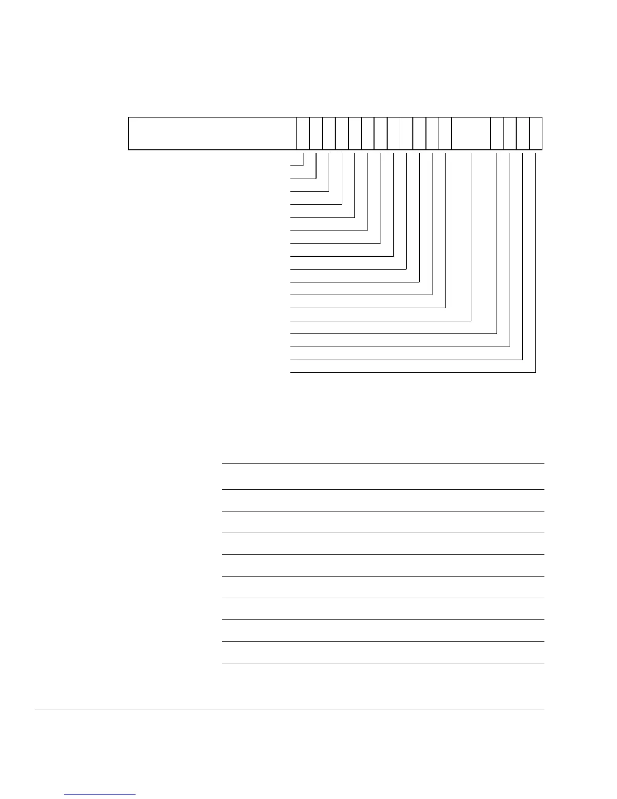
Figure 8-15 System Handler Control and State Register bit assignments
Table 8-21 describes the bit assignments of the System Handler Control Register.
31 3 1 0
USGFAULTENA
SVCALLPENDED
BUSFAULTENA
MEMFAULTENA
7811 101415161718
BUSFAULTPENDED
SYSTICKACT
PENDSVACT
MONITORACT
SVCALLACT
USGFAULTACT
BUSFAULTACT
MEMFAULTACT
13 12 246919
Reserved
MEMFAULTPENDED
USGFAULTPENDED
Reserved
Reserved
Reserved
Table 8-21 System Handler Control and State Register bit assignments
Bits Field Function
[31:19] - Reserved
[18] USGFAULTENA Set to 0 to disable, else 1 for enabled.
[17] BUSFAULTENA Set to 0 to disable, else 1 for enabled.
[16] MEMFAULTENA Set to 0 to disable, else 1 for enabled.
[15] SVCALLPENDED Reads as 1 if SVCall is pended.
[14] BUSFAULTPENDED Reads as 1 if BusFault is pended.
[13] MEMFAULTPENDED Reads as 1 if MemManage is pended.
[12] USGFAULTPENDED Read as 1 if usage fault is pended
[11] SYSTICKACT Reads as 1 if SysTick is active.