Trace Port Interface Unit
ARM DDI 0337G Copyright © 2005-2008 ARM Limited. All rights reserved. 17-21
17.3 Serial wire output connection
The Cortex-M3 TPIU provides a serial wire output mode that requires a single external
pin. There are three options available to connect this pin:
• A dedicated pin can be used for TRACESWO
• SWO shared with TRACEPORT
• SWO Shared with JTAG-TDO on page 17-22.
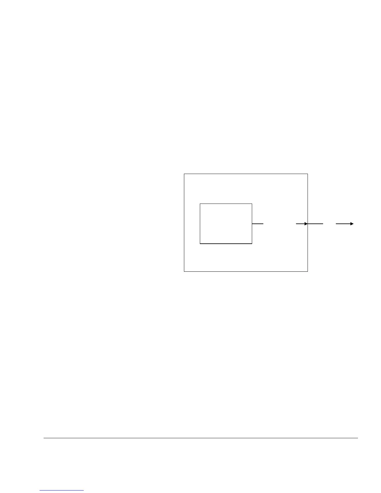
17.3.1 A dedicated pin can be used for TRACESWO
This is the simplest option, but it requires an extra package pin. Figure 17-14 shows the
dedicated pin option.
Figure 17-14 Dedicated pin used for TRACESWO
17.3.2 SWO shared with TRACEPORT
A pin can be shared between TRACEDATA[0] and TRACESWO. Because only one
of these two pins can be in use at any one time, there is no loss of functionality using
this option, and this is the preferred option when a dedicated trace port is present on the
package.
To implement this option, the SWOACTIVE output from Cortex-M3 TPIU is used to
control the multiplexor. Figure 17-15 on page 17-22 shows the SWO shared with
TRACEPORT option.
CM3TPIU
CortexM3Integration
TRACESWO SWV