Clocking and Resets
6-6 Copyright © 2005-2008 ARM Limited. All rights reserved. ARM DDI 0337G
Non-Confidential
Unrestricted Access
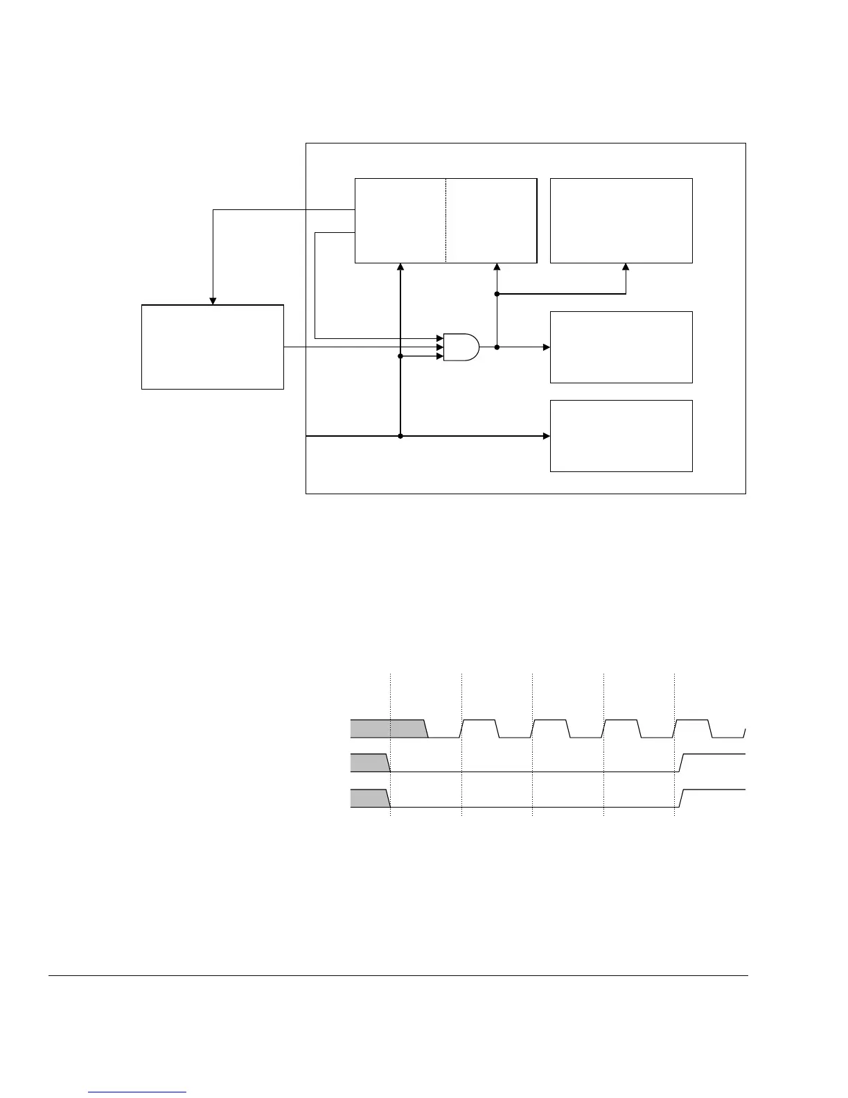
Figure 6-1 Reset signals
You must apply power-on or cold reset to the processor when power is first applied to
the system. In the case of power-on reset, the falling edge of the reset signal,
PORESETn, does not have to be synchronous to HCLK. Because PORESETn is
synchronized within the processor, you do not have to synchronize this signal.
Figure 6-2 shows the application of power-on reset. Figure 6-3 on page 6-7 shows the
reset synchronizers within the processor.
Figure 6-2 Power-on reset
It is recommended that you assert the reset signals for at least three HCLK cycles to
ensure correct reset behavior. Figure 6-3 on page 6-7 shows the internal reset
synchronization.
Cortex-M3
CM3CoreNVIC
System Components
(BusMatrix, MPU)
CORERESETn
NVICRESETnNVICDBGRESETn
SYSRESETREQ
VECTRESET
WATCHDOG
SYSRESETn
PORESETn
System Debug
Components
(FPB, DWT, ITM)
HCLK
PORESETn
nTRST